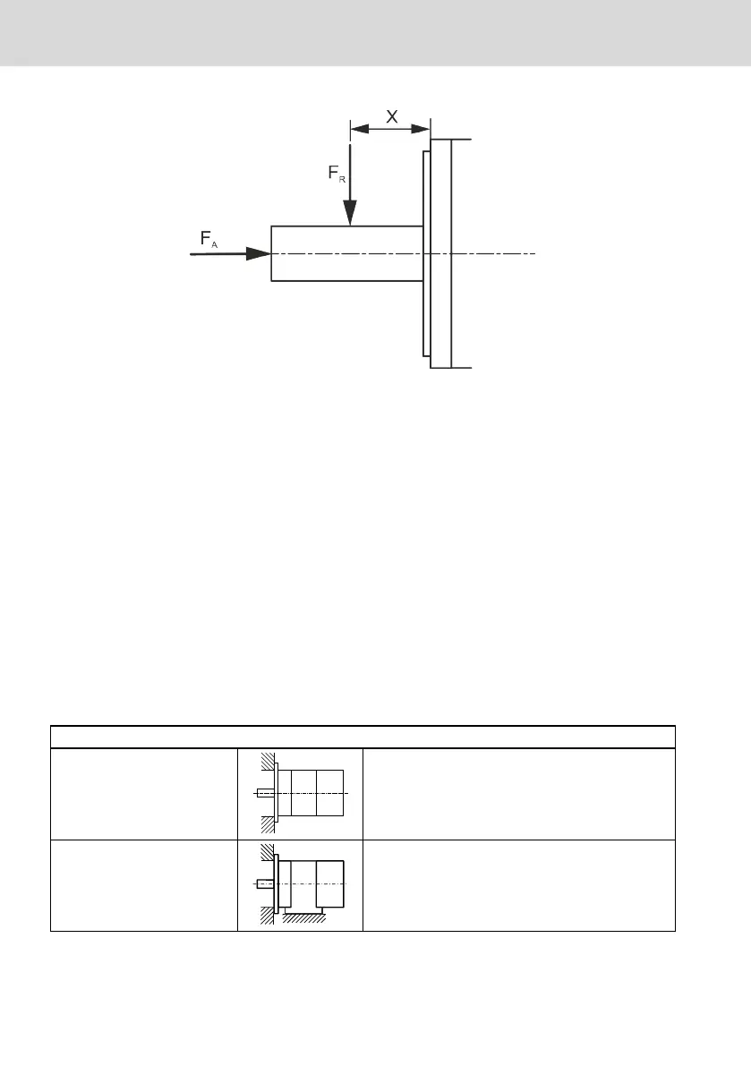
Fig. 4-11: Point of action of radial force F
R
and axial force F
A
The axial force values are the minimum permissible axial forces F
A
without limi-
tations. A detailed dimensioning is only possible if more boundary conditions
are known:
● Axial and radial force with force application point
● Installation position (horizontal, vertical with the shaft end pointing to the
top or bottom)
● Mean speed
Radial force diagrams are specified in the project planning manual "DOK-MO-
TOR*-MS2N*******-PRxx-xx-P"
4.2.12 Frame size, installation type
The motors can be installed horizontally and vertically with the shaft end point-
ing to the top or bottom. The installation variants correspond to IM-code accord-
ing to EN 60034-7 for frame size and installation type.
Code I / Code II (EN 60034-7)
IM B5 / IM 3001 Flange attachment on the drive side of the flange
IM B35 / IM 2001
(only MS2N13)
Foot installation, feet below, with additional flange
mounting on drive side of the flange
34/101
About this product
MS2N Synchronous Servomotors
Bosch Rexroth AG R911347581_Edition 04