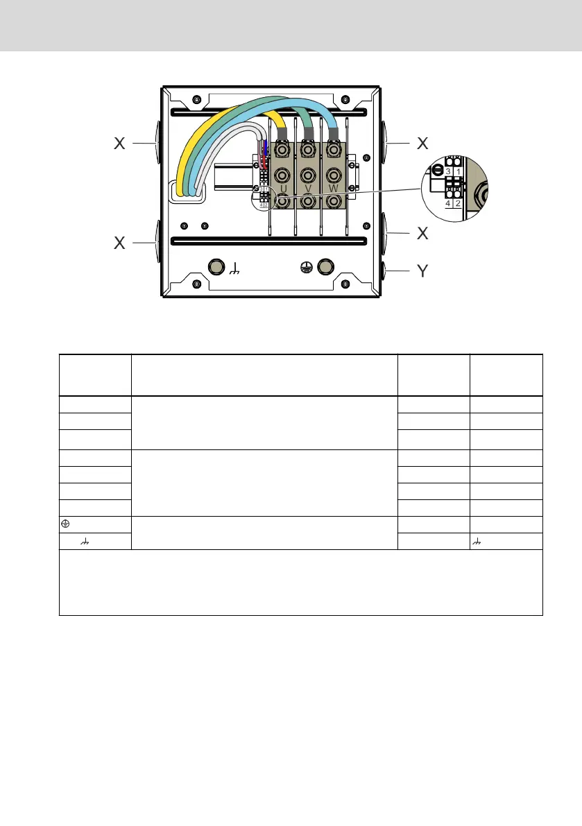
Fig. 6-5: MS2N terminal box "E"
Terminal boxes "E", power (double cable connection)
MS2N
1)2)
Clamp / data ctrlX /
IndraDrive
Cables RL2,
RLB2, REL, INK
3)
U Bolts M10, M
A
10 ... 20 Nm
Rated cross section 50 6 ... 120 mm
2
Rated current 269 A
A1 1
V A2 2
W A3 3
1
Tension spring connection 0.5 ... 2.5 mm
2
with wire end
ferrule
BD(+) 7
2 BD(-) 8
3 TP1(+) 5
4 TP2(-) 6
Screwed connection M10, M
A
10 Nm
PE GNYE
Shld Shld
1)
Terminal 1, 2 are not assigned for motors without holding brake.
2)
Terminal 3, 4 are not assigned for encoder Cx, Dx. The motor temperature is transmitted via the encoder inter-
face.
3)
Assign not used connection wires within the terminal box.
Tab. 6-27: MS2N Pin assignment terminal boxes "E"
MS2N Synchronous Servomotors 69/101
Assembly
R911347581_Edition 04 Bosch Rexroth AG