©2013 Brooks Automation Inc. Pub. No. 8040444, Rev. AA, 01/14/2013 ECO No. 63723 1-7
9600 Compressor Installation, Operation and Maintenance Instructions
General
The information in Table 1-4 provides general Compressor operating
specifications.
NOTE: The 9600 Compressor is designed for continuous operation and
should remain ON when the cryopumps are in a regeneration cycle.
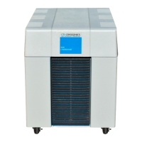
Component Description
The components of the 9600 Compressor that are accessible from the rear
panel are shown in Figure 1-4 and described in the following paragraphs.
Table 1-4: General Compressor Operating Specifications
Specification Values
Part Numbers 8135900G001
8135908G001
Input Power Cable
(Customer Supplied)
600 VAC
10 Gauge, 3 conductor wire with ground
Must conform to local electrical codes
Nominal Helium Pressure
Refer to
Table 4-1
Ambient Operating Tem-
perature Range
50 - 100º F (10 - 38º C)
Interface
Gas Supply Connector
Gas Return Connector
Remote Control Receptacle
Cryopump Power Receptacles: mates with the
BROOKS-CRYOGENICS supplied cryopump power cable for
single pump use.
Mates with remote junction box power cable for multiple
cryopump use.
1/2 in. Aeroquip self-sealing coupling
1/2 in. Aeroquip self-sealing coupling
24VAC, 2.7A inductive mates with P5 connector P/N MS3106A*
Adsorber Service Schedule 3 Years
* Supplied by BROOKS-CRYOGENICS