©2013 Brooks Automation Inc. Pub. No. 8040444, Rev. AA 01/14/2013 ECO No. 63723 3-5
Document Title
NOTE: Use a slotted screwdriver which is capable of holding a screw
when performing steps 9 and 10.
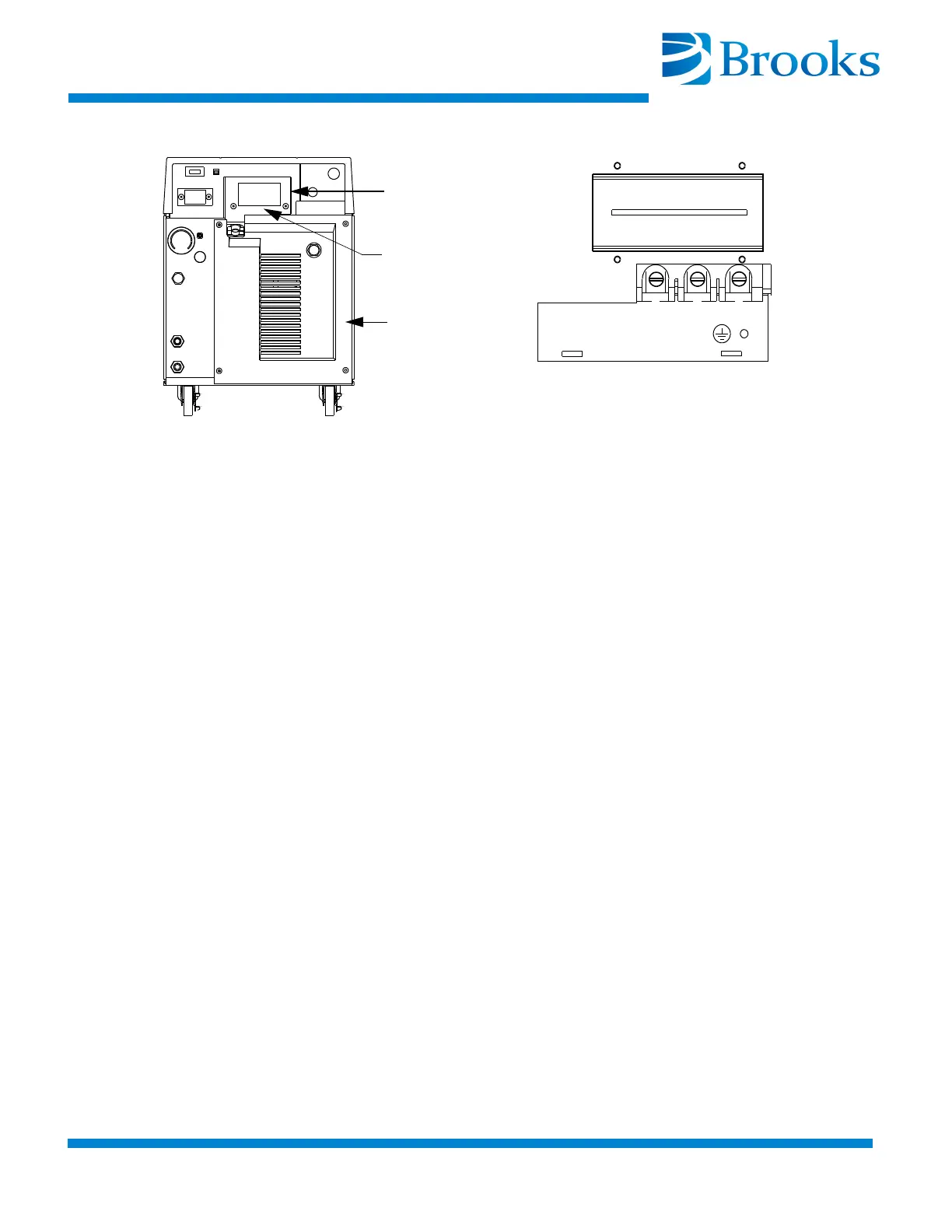
9. Remove the screws from the Compressor circuit breaker terminals
X, Y, and Z as shown in Figure 3-2.
Figure 3-2:
X
Y
Z
Detail A
See Detail A
Three Phase Power
Rear Panel
Circuit Breaker
Terminal Cover
9600 Compressor Circuit Breaker Terminals (Cover Removed)
NOTE: The phase order in which the conductor terminal lugs are
connected to circuit breaker terminals X, Y, and Z will be determined
during the Phase Check Procedure.
NOTE: For installation where one of the three phase legs is at or near
ground potential, connect that leg to terminal Y on the Compressor as
shown in Figure 3-2.
10. Install the conductor terminal lugs to the circuit breaker terminals
X, Y
, and Z as shown in Figure 3-2.
11. Torque the screws to 12 in.-lbs (0.14m-kg).
12. Allow enough cable to stay in the electrical enclosure to prevent
strain on the electrical co
nnections and tighten the screws on the
cable strain relief.
13. Install the power source end of the power cable according to the
local electrical codes.
14. Install the circuit breaker terminal cover.
15. Proceed with Phase Check.