Interfacing Polycold Cryochiller
24V DI/DO Remote Interface Installation and Operation Manual
Brooks Automation
5-24
214072 Revision B
24V DI/DO Remote Installation
1. Locate the remote control plug parts kit that shipped with the unit. Note that the cus-
tomer must provide a cable that is suitable for their interface requirements.
2. Slide the back shell of the connector over the cable.
3. Remove no more than 13mm (1/2 inch) of the outer cable jacket that covers the cable wire bundle.
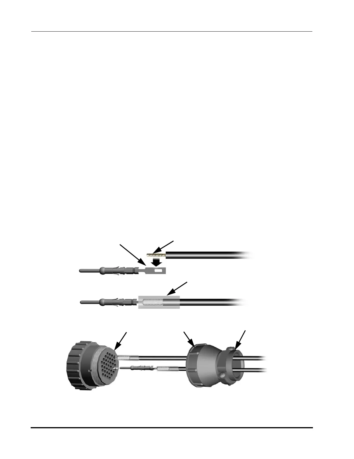
4. Strip 4mm (5/32 inch) of insulation from each of the wires and pre-tin each wire.
5. Solder each wire to the solder tail of a pin. Do not insert the wire into the hole on the solder tail.
6. Cut the heat shrinkable insulating tubes into 13mm (1/2-inch) lengths. Slide one of the insulation
tubes onto each soldered wire but do not shrink at this time.
7. Insert each pin into the appropriate contact socket on the back side of the connector. Push each pin
in until it clicks into place. Gently tug the wire to confirm the pin is properly inserted.
8. Slide the 13mm (1/2-inch) long insulating tubes down to the connector so that they cover the unin-
sulated wire and solder joint. Shrink the insulating tubes in place using a heat gun.
9. Thread the connector back shell onto the connector and screw it on until tightened firmly.
10. Install the cable clamp using the two screws provided and tighten it over the cable jacket so it firmly
holds the cable. The cable clamp may be reversed for large or small cables.
Connector
Wire Side
Connector
Back Shell
Cable Clamp
Shrinkable Insulating Tubing
Solder Tail
Tinned Lead
Figure 5-14: 24V DI/DO Remote Solder-tail Connector Wiring (non-isolated male pins shown)