Installation Polycold Cryochiller
Connect Electrical Power Installation and Operation Manual
Brooks Automation
4-14 214072 Revision B
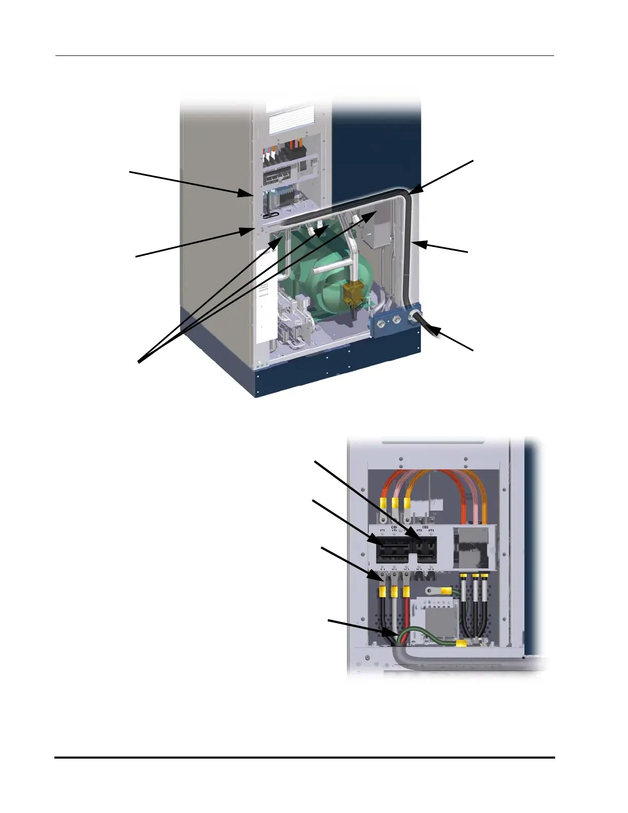
6. Attach 1/4 inch ring lugs to
each conductor on the
input power cable.
7. Remove the finger guard
from CB1 and CB2 as
required.
8. Connect the three phase
lines of the input power
cable to the lower termi-
nals / input side of CB1
using the provided screws
and washers (optional) in
the stack sequence shown
in Figure 4-10.
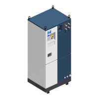
Figure 4-8: Power Cable Routing
Cable or wires
run in track
below shelf
Cable or wires
run behind
front frame
Cable
or wires
run up to
circuit
breaker
Cable connects to
customer provided
strain relief
Conduit connects to
customer provided
conduit connection
Cable Track
Screws
(3 places)
Confirm
protective
grommet
is in place.
CB1
CB2
Input
Power
Conductors
Ground
Conductor
Figure 4-9: Input Power Connections to CB1