NO.
IN
CHAPTER
8
FLOWCHART
AND
ERROR
STATUS
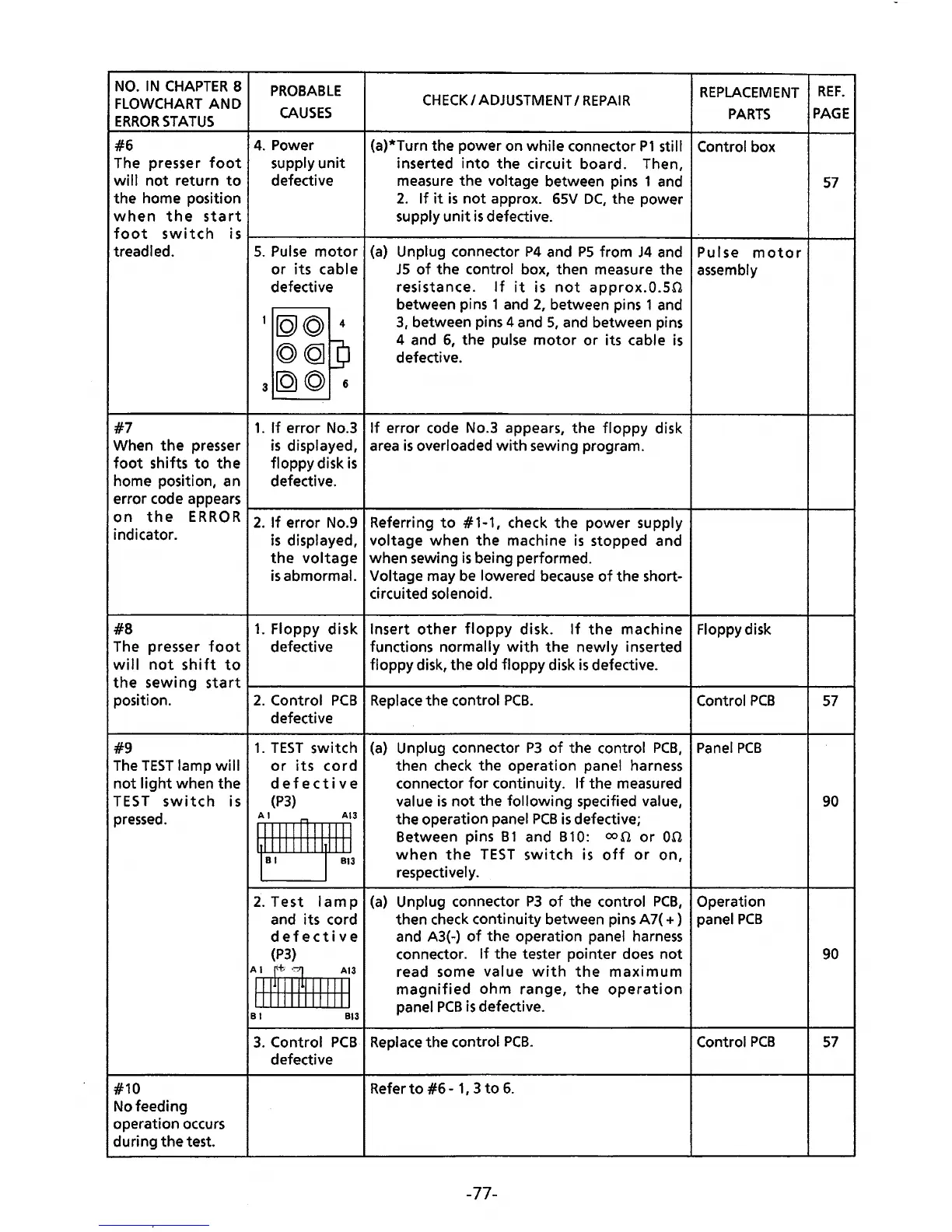
#6
The presser
foot
wi
II
not
return
to
the home position
when
the
start
PROBABLE
CAUSES
4.
Power
supply
unit
defective
CHECK
I
ADJUSTMENT
I
REPAIR
(a)*Turn the power on while connector
P1
still
inserted
into
the
circuit board. Then,
measure
the
voltage between pins 1 and
2.
If
it
is
not
approx.
65V
DC,
the power
supply
unit
is
defective.
REPLACEMENT
PARTS
Control box
REF.
PAGE
57
foot
switch
isr-----------+---------------------------------~----------~--~
treadled.
#7
5.
Pulse
motor
(a}
or
its
cable
defective
•[QJ©
4
©CQJ]
3
[Q)
© 6
Unplug connector
P4
and
PS
from
J4
and
JS
of
the control box, then measure
the
resistance.
If
it
is
not
approx.O.SO
between pins 1 and
2,
between pins 1 and
3,
between pins 4 and
5,
and between pins
4 and
6,
the pulse
motor
or its cable
is
defective.
1.
If
error No.3
If
error code No.3 appears,
the
floppy
disk
is
displayed, area
is
overloaded
with
sewing program.
floppy disk
is
defective.
Pulse
motor
assembly
When
the
presser
foot
shifts
to
the
home position, an
error code appears
on
the
ERR
0 R
1-2-.-lf-e-rr_o_r
-N-o-.9-+-R-e-fe-r-ri_n_g_t_o
__
#_1--1-,-,-h-e_c_k
_t_h_e_p_o_w_e_r-su_p_p_l
y--+-------+-~
indicator.
is
displayed, voltage
when
the
machine
is
stopped and
the
voltage
when sewing
is
being performed.
#8
The presser
foot
will
not
shift
to
is
abmormal. Voltage may
be
lowered
because
of
the short-
circuited solenoid.
1.
Floppy
disk
Insert
other
floppy
disk.
If
the
machine Floppydisk
defective functions
normally
with
the
newly
inserted
floppy disk, the
old floppy disk
is
defective.
the
sewing
start~-----------+----------------------------------~-----------~--~
position.
#9
The
TEST
lamp
will
not
light
when
the
TEST
switch
is
pressed.
#10
No feeding
operation occurs
during
the
test.
2.
Control
PCB
Replace
the.control
PCB.
defective
1.
TEST
switch
or
its
cord
defective
(P3)
~:
2.
Test
lamp
and its cord
defective
(P3}
A 1
~~
¥
All
111111111111
B 1
813
(a}
Unplug connector
P3
of
the control
PCB,
then check the operation panel harness
connector
for
continuity.
If
the measured
value
is
not
the
following
specified value,
the operation panel
PCB
is
defective;
Between pins
B1
and B10:
oon
or
00
when
the
TEST
switch
is
off
or
on,
respectively.
(a)
Unplug connector
P3
of
the control
PCB,
then check continuity between pins A7(
+)
and A3(-)
of
the operation panel
harness
connector.
If
the tester pointer
does
not
read some value
with
the
maximum
magnified
ohm
range,
the
operation
panel
PCB
is
defective.
3.
Control
PCB
Replace
the control
PCB.
defective
Refer
to
#6
-
1,
3
to
6.
-77-
Control
PCB
Panel
PCB
Operation
panel
PCB
Control
PCB
57
90
90
57