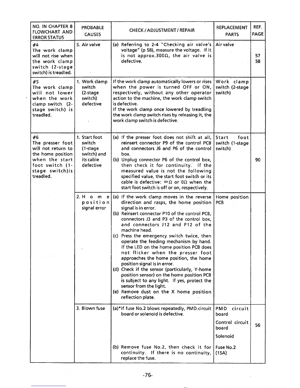
NO.
IN
CHAPTER.
8
FLOWCHART
AND
ERROR
STATUS.
#4
The
work
clamp
will
not
rise when
the
work
clamp
switch
(2-stage
switch)
is
treadled.
#5
The
work
clamp
will
not
lower
when
the
work
clamp switch (2-
stage
sw.i
tch)
is
treadled.
#6
The presser
foot
will
not
return
to
the home position
when
the
start
foot
switch
(1-
stage
switch)is
treadled.
PROBABLE
CAUSES
5.
Air
~alve
1.
Work
clamp
switch
(2-stage
switch)
defective
1.
Start
foot
switch
(1-stage
switch) and
its cable
defective
CHECK
I
ADJUSTMENT
I
REPAIR
REPLACEMENT
PARTS
(a)
Referring
to
2-4
"Checking
air
valve's
Air
valve
voltage" (p
58),
measure
the
voltage. If.
it
is
not
approx.300n,
the
air
valve
is
defective.
If
the
work
clamp automatically lowers
or
rises
Work
cIa
m p
when
the
power
is
turned
OFF
or
ON, switch (2-stage
respectively,
without
any
other
operator
switch)
action
to
the machine,
the
work
clamp switch
is
defective.
If
the
work
clamp once lowered by treadling
the
work
clamp switch
rises
by releasing
it,
the
work
clamp switch
is
defective.
(a)
If
the
presser
foot
does
not
shift
at
all,
reinsert connector
P9
of
the ·control·
PCB
and connectors
JG
and
P6
of
the
control
box.
(b) Unplug connector
P6
of
the control box,
then
check
it
for
continuity.
If
the
measured
value
is
not
the
following
specified value, the start
foot
switch
or
its
cable
is
defective:
con
or
on
when
the
start
foot
switch
is
off
or
on, respectively.
Start
foot
switch
(1-stag~
switch)
2.
H o m e
(a}
If
the
work
clamp moves in
the
reverse Home position
posit
i o n
direction
and rasps,
the
home position
PCB
signal error signal
is
in error.
(b) Reinsert connector
P1
0
of
the control
PCB,
connectors
J3
and
P3
of
the control box,
and
connectors
J
12
and
P12
of
the
machine head.
(c)
Press
the emergency switch
twice,
then
operate
the
feeding mechanism by hand.
If
the
LED
on
the
home position
PCB·does
not
flicker
when
the
presser
foot
approaches
the
home position,
the
home
position signal
is
in error.
(d)
Check
if
the
sensor (particularly, Y-home
position sensor) on
the
home position
PCB
is
subject
to
any light.
If
yes,
protect the
sensor from
the
light.
(e)
Remove
dust
on
the
X
home
position
reflection plate.
3.
Blown fuse
(a)*lf
fuse No.2 blows repeatedly, PMD.circuit PM D
circuit
board
or
solenoid
is
defective. board
Control
circuit
board
Solenoid
(b) Remove fuse No.2,
then
check
it
for
Fuse
No.2
continuity.
If
there
is
no
continuity,
(15A)
replace
the
fuse.
-76-
REF.
PAGE
57
58
90
56