3-57
Confidential
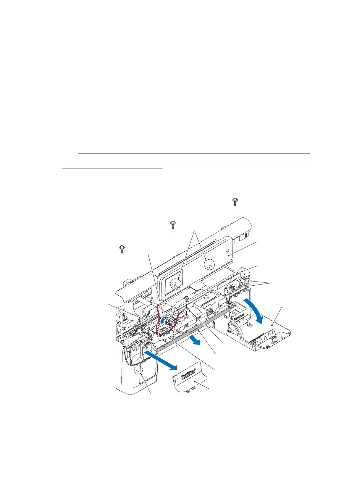
9.7 Front Plate and Control Panel ASSY
(1) Open the ink cartridge cover.
(2) Release the hook and remove the front plate.
(3) Remove the three screws of the TAPTITE CUP B M3x10.
(4) Pull out the disc guide.
(5) Release the 2 hooks on the right side of the control panel ASSY, the 2 hooks on the lower side,
and 1 hook on the left side to pull out the control panel ASSY upwards.
Note The control panel ASSY is connected to the machine by harnesses. Do not attempt to pull it
away from the main unit.
(6) Release the connector lock and unplug the LCD flat cable from the main PCB.
Note After disconnecting the LCD flat cable, check if the cable is not damaged at its end or short-
circuited. When connecting LCD flat cables, do not insert them at an angle. After insertion, check
again that the cables are not at an angle.
(7) Remove the screw of the TAPTITE CUP S M3x6 and remove the FG wire from the cable guide.
Assembling Note
• Route the FG wire along the cable guide (marked by the dotted circle) as shown above.
• After installing the control panel ASSY in the upper cover, confirm that the there is no gap
between the front ends of the control panel ASSY and the upper cover.
“b”
(3_078)
Disc guide
FG wire
Ink cartridge cover
Control panel ASSY
Front plate
Upper cover
Hook
Release the
connector lock
Hook
Hook
"a": TAPTITE CUP S M3x10
"b": TAPTITE CUP S M3x6
"a"
"a"
"a"
"b"
LCD flat cable
Cable guide
 Loading...