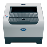
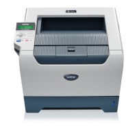
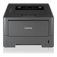
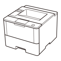
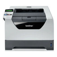
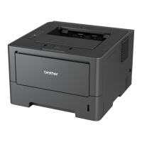
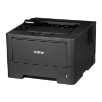
HL-5240/5250DN/5270DN/5280DW SERVICE MANUAL
vii Confidential
CHAPTER 6 ADJUSTMENTS AND UPDATING OF SETTINGS,
REQUIRED AFTER PARTS REPLACEMENT.................. 6-1
1. IF YOU REPLACE THE MAIN PCB ..........................................................................6-1
2. IF YOU REPLACE THE PERIODICAL MAINTENANCE PARTS ............................ 6-10
CHAPTER 7 SERVICE SUPPORT SOFTWARE.................................... 7-1
1. CONTROL PANEL ....................................................................................................7-1
1.1 Users Mode...................................................................................................................... 7-1
1.2 User Maintenance Mode.................................................................................................. 7-3
1.3 Service Mode ................................................................................................................... 7-5
2. HIDDEN FUNCTION MENUS .................................................................................7-15
2.1 Professional Menu ......................................................................................................... 7-16
2.2 Reset Parts Life Menu ................................................................................................... 7-23
2.3 Service Menu ................................................................................................................. 7-24
3. NVRAM DEFAULT VALUE......................................................................................7-29
APPENDIX
1. MAIN PCB CIRCUIT DIAGRAM ............................................................................... A-1
2. LOW-VOLTAGE POWER SUPPLY PCB CIRCUIT DIAGRAM (100V, 200V).......... A-8
3. HIGH-VOLTAGE POWER SUPPLY PCB CIRCUIT DIAGRAM ............................. A-10
4. POINT TO POINT CONNECTION DIAGRAM........................................................ A-11
5. GEAR LAYOUT DRAWING.................................................................................... A-12
6. READMARKS......................................................................................................... A-14
7. LOCATION OF THE FERRITE CORE ................................................................... A-15
8. HL-5240L................................................................................................................ A-18
 Loading...


