5-69
Confidential
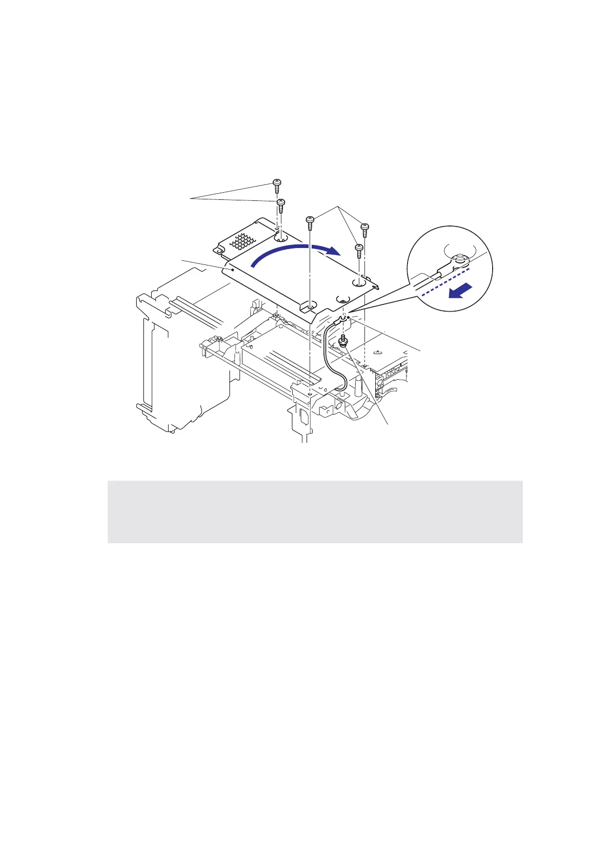
8.27 PS PCB Unit
(1) Turn the Printer upside down.
(2) Remove the five bind B M4x12 Taptite screws, and then remove the Base plate LV.
(3) Remove the Screw pan (S/P washer) M3.5x6 from the Base plate LV to remove the PS
PCB unit terminal.
Fig. 5-92
Assembling Note:
• When assembling the Base plate LV, Direct the cable side of the PS PCB unit terminal
to the backward (Fig. 5-91: To the direction of an arrow of the enlarged illustration.), and
align parallel the PS PCB unit terminal with the side of the Base plate LV.
PS PCB unit terminal
Screw pan (S/P washer) M3.5x6
Taptite bind B M4x12
Base plate LV
<Back side>
Taptite bind B M4x12

 Loading...