3-27
Confidential
LCD model
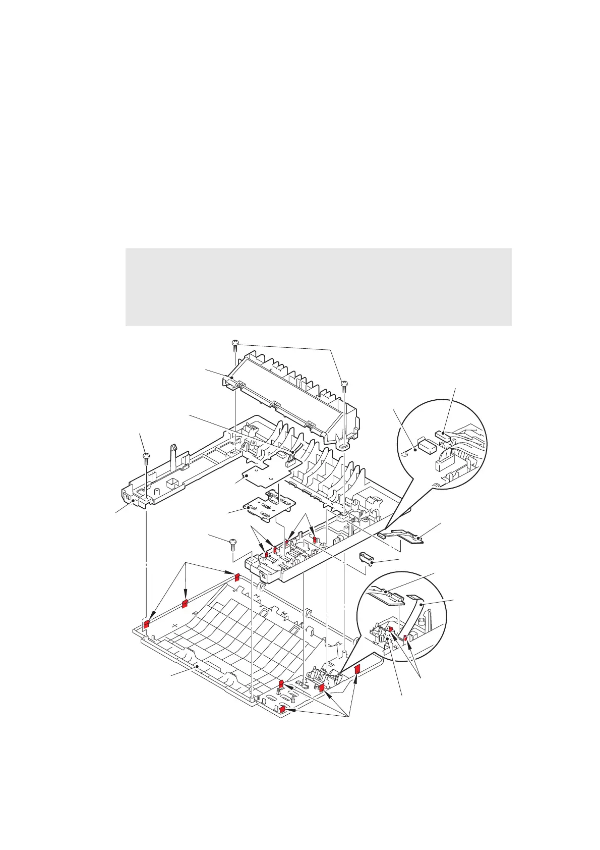
(1) Release the panel harness from the securing fixtures.
(2) Disconnect the backlight harness from the panel PCB ASSY, release the four hooks, and
remove the panel PCB ASSY from the top cover base.
(3) Remove the rubber key printed ASSY and the panel light guide.
(4) Remove the two taptite bind B M4x12 screws "a", and remove the inner chute ASSY
from the top cover ASSY.
(5) Disconnect the LCD harness, release the two hooks, and remove the backlight PCB
ASSY from the LCD holder.
(6) Remove the two taptite bind B M4x12 screws "b", release the seven hooks, and remove
the top cover base from the top cover ASSY.
Fig. 3-25
Harness routing: Refer to “1.Main PCB ASSY”.
Note:
• After disconnecting the flat cable(s), check that the end of each cable is not
damaged or short-circuited.
• When connecting the flat cable(s), insert it straight. After insertion, check that the
cable is not at an angle.
Inner chute ASSY
Taptite bind B M4x12 screws “a”
Backlight harness
Panel PCB
ASSY
Backlight PCB ASSY
LCD harness
Hooks
Hooks
Top cover ASSY
Hooks
Panel PCB ASSY
Rubber key
printed ASSY
Taptite bind B M4x12 screws “b”
Taptite bind B
M4x12 screws “b”
Panel light guide
Backlight PCB ASSY
LCD holder
Hooks
Panel harness
Top cover base
Hooks
 Loading...