7-5
Confidential
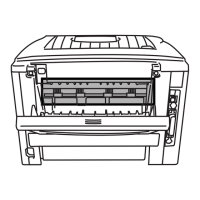
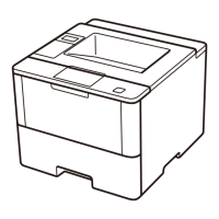
(10) Release the heater harness of the fuser unit from the guide on the main frame R, and
disconnect the heater harness from the low-voltage-heater harness.
Fig. 7-6
Harness routing: Refer to “3.Fuser unit”.
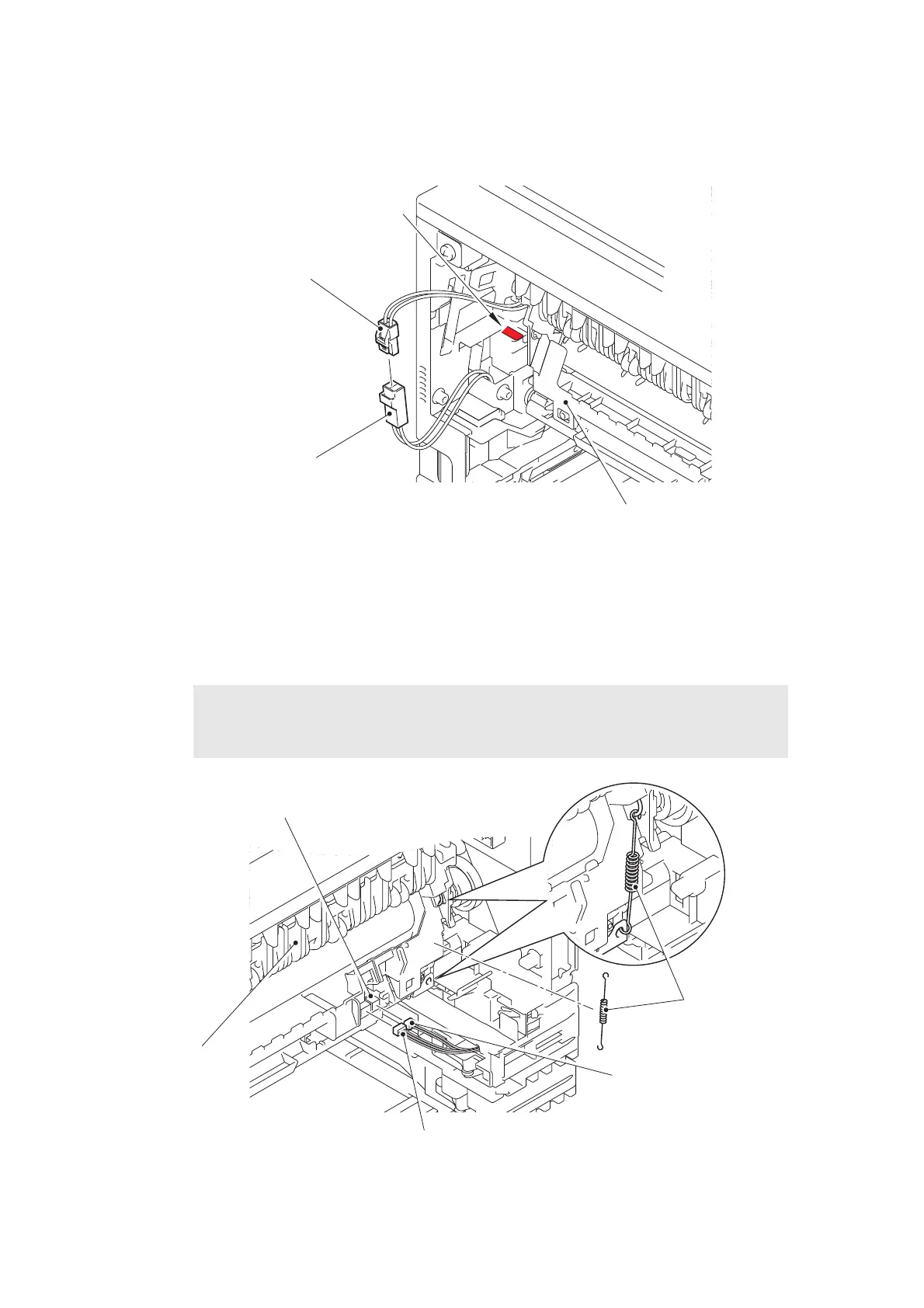
(11) Remove the fuser unit ground spring from the fuser unit.
(12) Release the center thermistor harness and the side thermistor harness of the fuser unit
from the guide, and disconnect these harnesses from the eject sensor PCB ASSY.
Fig. 7-7
Harness routing: Refer to “3.Fuser unit”.
Note:
• When disconnecting the harness, hold the top of the PCB connector to prevent the
PCB connector being damaged.
Heater harness
Fuser unit
Low-voltage-heater harness
<Frame R side>
Guide
Center thermistor
harness
Eject sensor PCB ASSY
Side thermistor harness
Fuser unit
<Frame L side>
Fuser unit ground
spring

 Loading...