117
SYSTEM ANALYSIS
EMM DIAGNOSTICS
5
EMM DIAGNOSTICS
Access EMM information using the EMM’s LED
indicators and the diagnostic program.
EMM turned ON is verified through LED display or
communication with diagnostic software.
To access EMM information using the diagnostic
software, connect interface cable to diagnostic
plug and turn key switch ON. Battery cables and
battery must be connected to supply power to
EMM.
LED Indicators
Activation of LED indicators on the EMM corre-
spond to specific EMM circuits.
IMPORTANT: LED 1 is toward the rear of the
outboard (Closest to EMM J2 connector).
Starting Mode
Light ON indicates system is functioning properly.
• LED 1 – Light ON, Stator signal 30 V or higher,
“CHARGING OKAY”
• LED 2 – Light ON, CPS output, “CRANK POSI-
TION OKAY”
• LED 3 – Light ON, Sensor/5 V circuits, “SEN-
SORS OKAY”
• LED 4 – Light ON, Lanyard/Stop circuit not
grounded, “LANYARD/STOP OKAY”
Refer to EMM DIAGNOSTICS on p. 104 for addi-
tional diagnostic information.
Running Mode
Light ON indicates system is MALFUNCTIONING.
• LED 1 – Light ON, charging output malfunction
12 V or 55 V circuit; or SAC overcurrent
“CHARGING FAULT”
• LED 2 – Light ON, Injector or ignition circuit
malfunction, “INJECTOR/IGNITION FAULT”
• LED 3 – Light ON, Sensor/5 V circuits, “SEN-
SOR FAULT”
• LED 4 – Light ON, “NO OIL /OVERHEAT
FAULT”
Refer to EMM DIAGNOSTICS on p. 104 for addi-
tional diagnostic information.
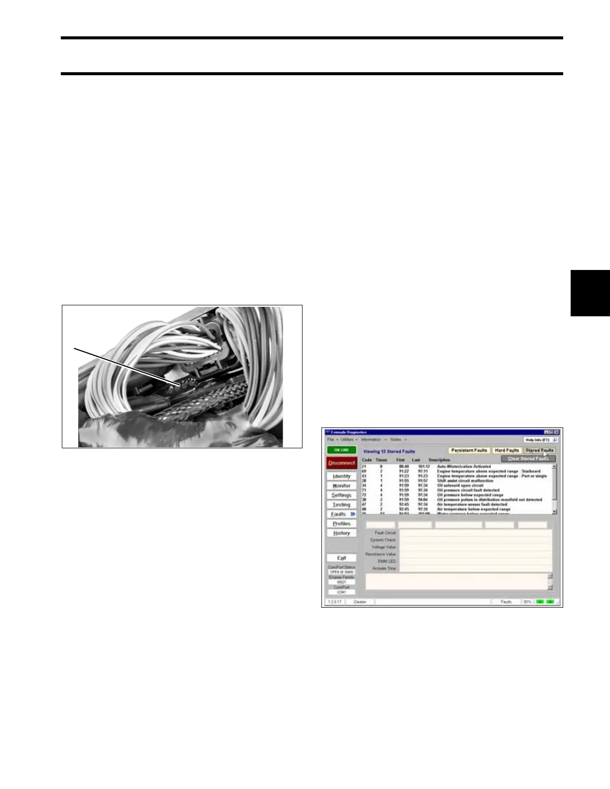
Software Programs
The Evinrude Diagnostics Software program can
be used to communicate with the EMM. Commu-
nication also requires a 12 V supply to power up
the EMM.
Refer to EMM DIAGNOSTICS on p. 104 for addi-
tional diagnostic information. Identify and resolve
all problems related to Stored Faults/Codes. Note
all Stored Faults/Codes prior to clearing the
codes.
1. LED indicators 005239
1
Stored Faults Review Screen 005143