206
OILING SYSTEM
COMPONENTS
Oil Supply and Distribution Diagrams – V6
1.
2.
3.
4.
5.
6.
7.
8.
Oil tank assembly
Oil pick-up
Oil supply hose
In-line oil filter
Oil injector assembly
Oil distribution hoses
Oil pressure sensor
Rear oil manifold
Rear oil manifold delivers oil to:
- Upper main bearing
- #1, #2, #3, #4, #5 and #6 cylinder sleeves
Primary oil manifold delivers oil to:
- Auxiliary oil manifold
- #1, #2, #3, #4, #5 and #6 crankcase fittings
6
8
3
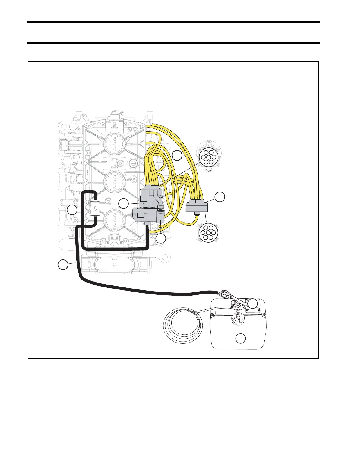
Oil Injector / Hose Routing Diagram
150-200HP/60ºV6- Evinrude E-TEC
1
2
3
45
6
7
Primary Oil
Manifold
Rear Oil
Manifold
1
2
3
45
6
7
1. Cylinder 2
2. Cylinder 4
3. Cylinder 6
4. Cylinder 5
5. Cylinder 3
6. Cylinder 1
7. Upper main bearing
1. Cylinder 6
2. Cylinder 5
3. Cylinder 4
4. Cylinder 1
5. Cylinder 2
6. Cylinder 3
7. Auxliary oil manifold
1. Oil tank assembly
2. Oil pick-up
3. Oil supply hose
4. Oil filter
5. Oil pump assembly
6. Oil distribution hoses
7. Oil pressure switch
8. Auxiliary oil manifold
4
5
1
2
7
005357