140
ELECTRICAL AND IGNITION
CAPACITOR TEST
STEP 2
Connect red meter lead to terminal “A” and black
meter lead to terminal “C.” Rotate the sensor lever
through its range of travel. Resistance reading
must change evenly as the sensor lever is moved.
STEP 3
Connect red meter lead on terminal “B” and black
meter lead to terminal “C.” Rotate the sensor
lever. Resistance reading must change evenly as
the sensor lever is moved.
Engine Temperature Sensor Test
Use an ohmmeter to measure resistance.
Air Temperature Sensor (AT) Test
Use an ohmmeter to measure resistance.
CAPACITOR TEST
The capacitor should charge when you use an
ohmmeter on the high ohms scale with the proper
polarity. The resistance will increase until it goes
to (nearly) infinity. If the capacitor is shorted, then
it will never charge. If it is open, the resistance will
be infinite immediately and won't change. If the
polarity of the probes is reversed, it will not charge
properly either. Determine the polarity of your
meter and mark it. Black is usually negative with
VOMs, for example. Confirm with a marked diode.
A low reading across a good diode indicates that
the positive lead is on the anode (triangle) and
negative lead is on the cathode (bar).
Engine Temperature Sensor Resistance
9000 to 11000 Ω @ 77°F (25°C)
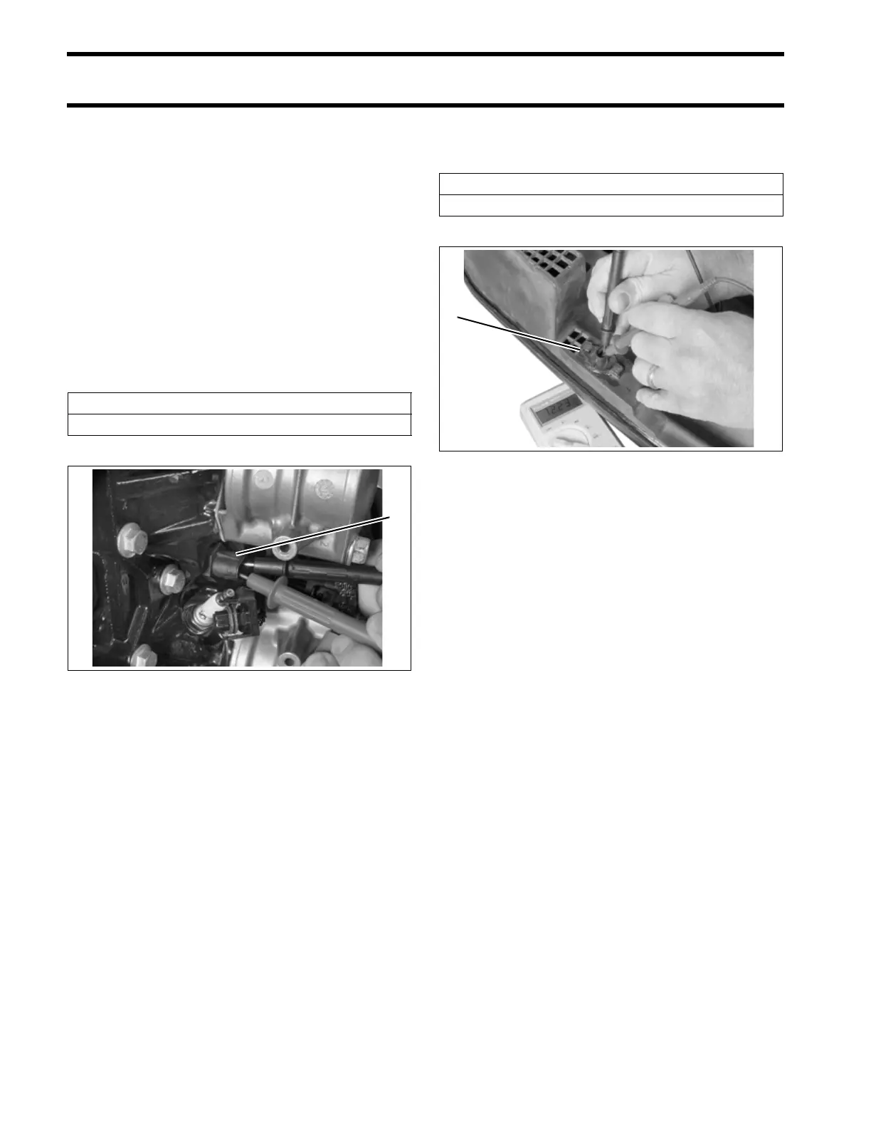
1. Engine temperature sensor (2) 004196
1
AT Sensor Resistance
9000 to 11000 Ω @ 77°F (25°C)
1. AT sensor 004216
1