128
SYSTEM ANALYSIS
IGNITION OUTPUT
System Voltage
The ignition module of the EMM is powered by the
55 V system.
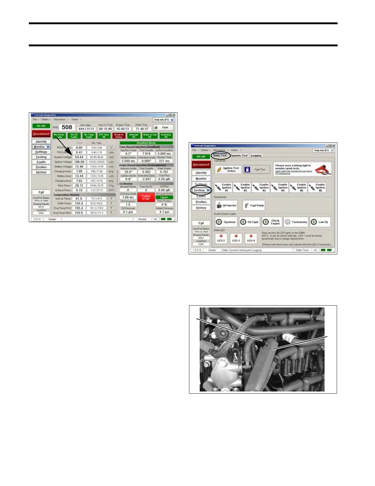
Use the engine Monitor screen of the Evinrude
Diagnostics Software program to check system
voltage.
Results:
• “KEY ON” - 30 V ± 2, system voltage is GOOD
• “KEY ON” - less than 30 V ± 2, check 12 V
power to EMM. Repair connection or wiring.
Possible faulty SAC circuit in EMM.
• “RUNNING” - 55 V ± 2, system voltage is GOOD
• “RUNNING” - less than 55 V ± 2, check stator
output to EMM. Repair connection or wiring.
Possible faulty stator or EMM. Refer to STATOR
TESTS on p. 141.
IMPORTANT: EMM must be ON for voltage to
be present on the system voltage (55 V) circuit.
This output supplies all 55 V circuits on the
engine, including the ignition module of the EMM.
Power is normally supplied to the EMM when the
key switch is ON. Switched B+ (12 V) is supplied
to the engine wire harness. Voltage enters the
EMM at pin 21 (purple) of the EMM J1-B connec-
tor. Pin 9 (black) of the EMM J1-B connector pro-
vides ground to the EMM.
Static Spark Test
Perform the static spark test using the Evinrude
Diagnostics Software program and timing light.
IMPORTANT: DO NOT use a spark checker tool
with E-TEC models. Radio Frequency Interfer-
ence (RFI) generated by the arcing current can
cause erratic behavior in the EMM.
The outboard must NOT be running and the emer-
gency stop switch lanyard must be installed.
Connect timing light pickup to primary and then
secondary circuit of the ignition circuit being acti-
vated. Activate one circuit at a time and observe
timing light strobe for consistent flash.
Engine Monitor Screen, System Voltage 005141
Testing, Static Test Screen 005146
1. Timing light pick-up
2. Ignition coil primary wire
005318
1
2