177
FUEL SYSTEM
COMPONENTS
7
COMPONENTS
The Evinrude E-TEC direct injection system con-
sists of the following components:
• Fuel Lift Pump
• Fuel Filter
• Vapor Separator
• Fuel Circulation Pump
• Fuel Supply Manifolds
• Fuel Injectors
• Fuel Return Manifolds
Fuel Lift Pump
The fuel lift pump is a mechanical, pressure-pulse
pump. The diaphragm of the pump is driven by
two pulse hoses that connect to the front of the
cylinder/crankcase assembly.
Fuel lift pump pulse hose locations:
• V4 models: cylinders 2 and 4
• V6 models: cylinders 4 and 6
Vacuum from the fuel lift pump pulls fuel from the
fuel tank. Once fuel reaches the pump, internal
pump pressure forces the fuel from the pump
through the fuel filter and into the vapor separator.
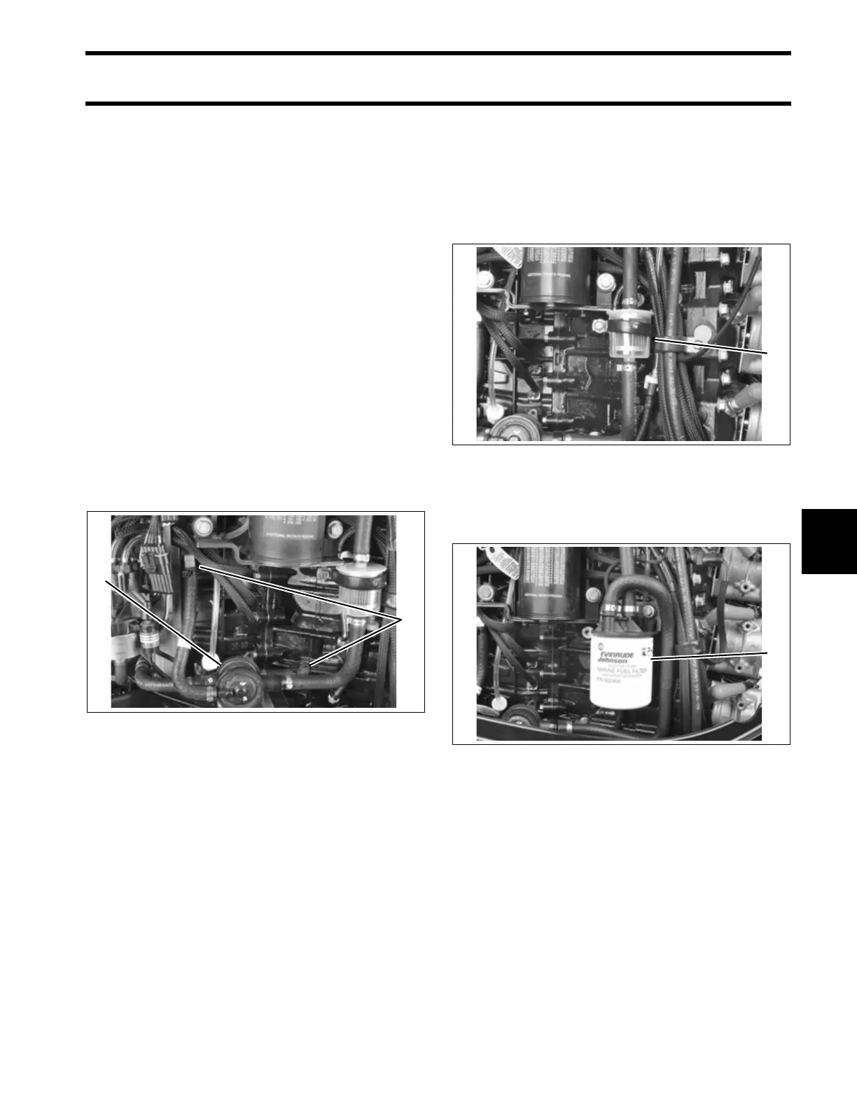
Fuel Filter
The fuel filter protects the vapor separator and the
high-pressure components of the fuel system from
water and contaminants. Refer to INSPECTION
AND MAINTENANCE SCHEDULE on p. 80 for
service frequency.
Accessory kit, P/N 5007045, is available to add a
water-separating cannister fuel filter to Evinrude
E-TEC 60° V outboards.
1. Fuel lift pump
2. Pulse hose fittings
005261
2
1
1. In-line fuel filter 005234
1. Water-separating fuel filter 005237
1
1