314
GEARCASE
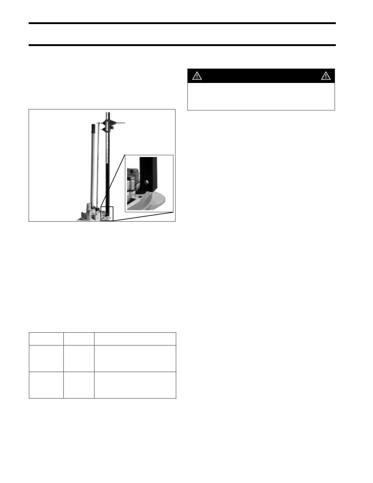
SHIFT ROD ADJUSTMENT
SHIFT ROD
ADJUSTMENT
Check the shift rod height from the shift rod hole to
the surface of the gearcase using Universal Shift
Rod Height Gauge, P/N 389997.
With the shift rod and detent lever in NEUTRAL,
rotate the shift rod up or down as necessary for
correct adjustment. Once correct height is
achieved, rotate rod one half turn or less to face
offset forward.
IMPORTANT: The NEUTRAL detent is a two-
step design. Make sure the NEUTRAL detent ball
is in the center step before checking shift rod
height.
Shift Rod Heights
DISASSEMBLY
IMPORTANT: Clean and inspect all components
during disassembly. Replace any damaged com-
ponents, seals, O-rings, and gaskets upon assem-
bly.
Remove the propeller and mounting hardware.
Drain and inspect oil as described in LUBRICANT
on p. 307.
Remove gearcase as described in REMOVAL
AND INSTALLATION on p. 308.
Remove water pump as described in WATER
PUMP on p. 311.
Pre-Disassembly Inspection
Before disassembling the gearcase, examine the
following:
• Gearcase Housing — Check for visible dam-
age to skeg, strut, anti-ventilation plate, bullet,
and mating surface. Check seal areas for visible
signs of lubricant leakage.
• Propeller Shaft — Check for bent or damaged
shaft. Check for twisted splines and damaged
threads.
• Shift Rod — Check for misadjusted, bent, or
binding rod. A misadjusted shift rod height can
cause shift difficulty, loss of boat and outboard
control, and gearcase damage.
COA6166
Model Type Height
20 in. (L)
“S2” (V4)
“O” (V6)
“L” (V6)
20 15/16 in.
(20.945 in./ 532 mm)
± 1/2 Half Turn
25 in. (X)
“O” (V4)
“M” (V6)
25 15/16 in.
(25.945 in./659 mm)
± 1/2 Turn
WARNING
Wear safety glasses to avoid personal
injury, and set compressed air pressure to
less than 25 psi (172 kPa).