130
SYSTEM ANALYSIS
IGNITION OUTPUT
Ignition Primary Circuit
Resistance Test
Disconnect the battery cables at the battery.
Calibrate ohmmeter to low ohms scale.
With key switch OFF, remove the EMM J1-B con-
nector and measure resistance of each primary
circuit. Note resistance reading between each pri-
mary wire and ground. Refer to engine wiring dia-
gram.
IMPORTANT: A reading of less than 2 ohms is
acceptable. Make sure meter is calibrated to read
1 ohm or less.
Results:
Primary circuit (complete circuit) resistance read-
ing is higher than 2 Ω:
• Repair primary circuit wiring or coil grounds as
needed and retest.
• Replace faulty coils or wiring.
Primary circuit resistance reading less than 2 Ω or
within specification and EMM ignition output volt-
age is 130 V or higher:
• Refer to Secondary Winding Resistance Test
on p. 141. Repair high tension spark plug lead
or replace ignition coil and/or high tension spark
plug lead assembly.
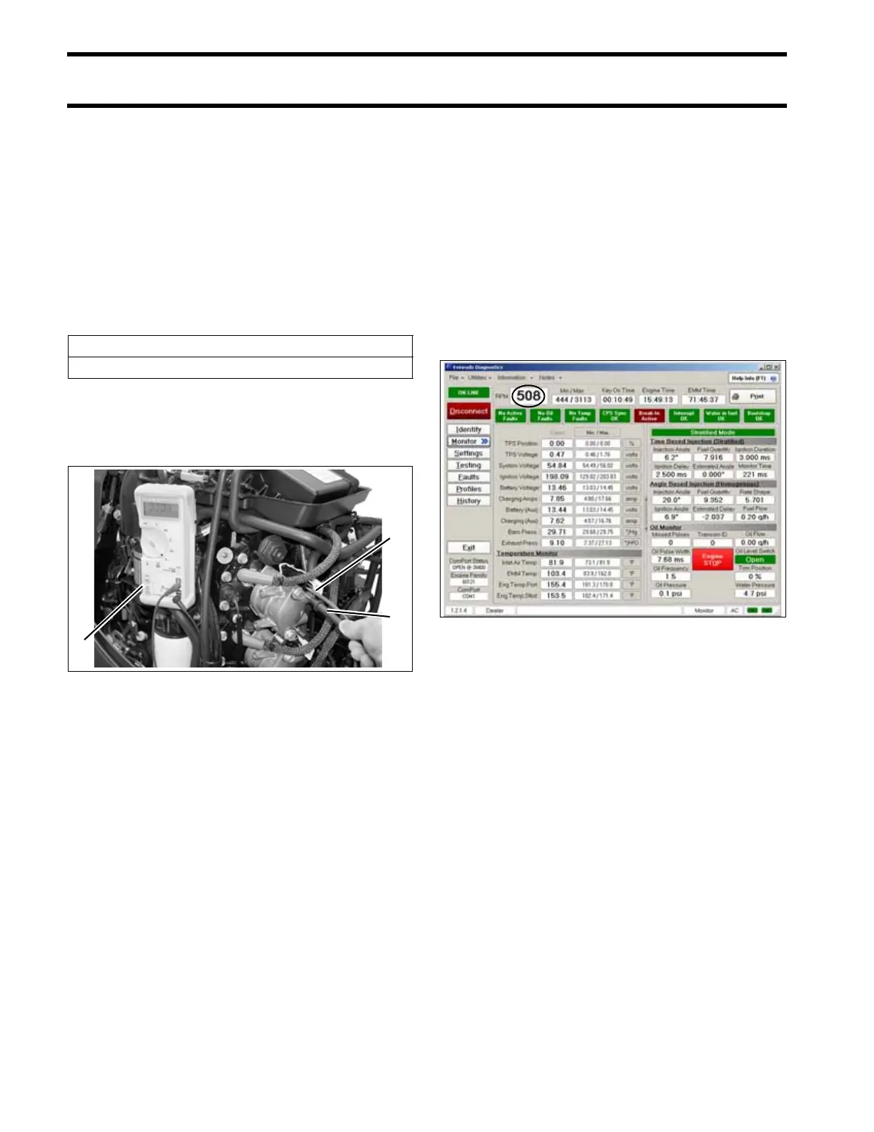
Crankshaft Position Sensor (CPS)
Test
Use the Evinrude Diagnostics Software program
to check RPM reading. An RPM display higher
than zero indicates a CPS signal to the EMM.
Cranking RPM is typically 175 RPM.
Observe Engine RPM and Power ON Time dis-
play fields of the engine Monitor screen. “ON
Time” should be continuous and should not reset
unless the key switch is turned OFF or power to
the EMM is interrupted.
Check CPS resistance (560 Ω ± 10%). Make cer-
tain ohmmeter is calibrated properly. Refer to
Crankshaft Position Sensor (CPS) Test on
p. 139.
Ignition Coil Primary Circuit Resistance
0.090 ± 0.005 Ω.
1. Ohmmeter, low ohms scale
2. Red meter lead, with pin adapter
3. Black meter lead to ground
005440
2
3
1
Engine Monitor Screen, Engine RPM display 005141