PULSE Multi-analyzer System Type 3560-B/C/D/E – Installation and IDAe Hardware90
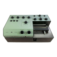
7.5 BNC Output Connector
Fig.7.5
BNC output connector
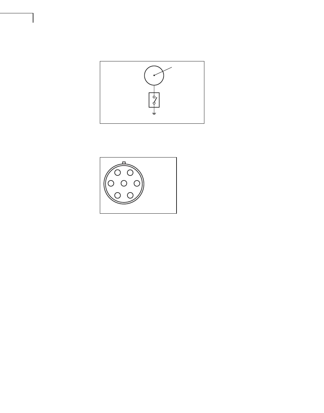
7.6 7-pin LEMO Connector
Fig.7.6
7-pin LEMO connector
Pin 1: Calibration output (charge injection
calibration check)
Pin 2: Signal ground
Pin 3: Polarization voltage (0 or 200 V)
Pin 4: Signal input
Pin 5: Transducer identification
Pin 6: Power supply positive (+15 V)
Pin 7: Power supply negative (–15 V)
Housing: Chassis
980319/2
Signal Output
Signal GND
Floating/Grounded
Internal Switch
(controlled by software)
Chassis
942095/2
7
16
5
43
2
 Loading...