CHAPTER 7
Connectors, Controls and Indicators
93
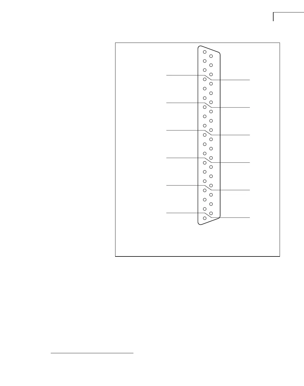
Fig.7.9
D-sub connector of Types
3039-B, 3041-B
7.8 Overload
The overload LEDs in the input/output modules serve a number of functions and do not
simply indicate signal overload. Possible indications include
a
:
• Signal overload
Signal overload is caused by signals levels that are too high for the signal analysis
chain to handle. Overload can be caused by both in-band signals and out-of-band sig-
nals, referring to the frequency range selected for data acquisition and analysis.
The signal overload is designed to always indicate overload whenever signal is in risk
of being distorted or clipped.
For “in-band frequencies”, overload will be indicated for signal levels exceeding the
040350/1
CIV
= Charge Insert Voltage
+
Vpre
= Preamplifier Power Supply:
+
15V
Vpre
= Preamplifier Power Supply:
–
15V
Lgnd = Local Ground (Signal reference)
13
19
18
17
16
15
14
12
11
10
9
8
7
6
5
4
3
2
1
Vpol
– Vpre
Lgnd
+ Vpre
– Vpre
+ Vpre
– Vpre
+ Vpre
– Vpre
+ Vpre
– Vpre
+ Vpre
– Vpre
+ Vpre
Lgnd
CH 1
CH 2
CH 3
CH 4
CH 5
CH 6
Lgnd
Lgnd
Lgnd
Lgnd
32
37
36
35
34
33
31
30
29
28
27
26
25
24
23
22
21
20
Signal
CIV
Signal
CIV
Signal
CIV
Signal
CIV
Signal
CIV
Signal
CIV
Vpol = Polarization Voltage (0 or 200V, all channels)
Housing: Chassis
Transducer Identification
Transducer Identification
Transducer Identification
Transducer Identification
Transducer Identification
Transducer Identification
a. See the modules’ specifications in Chapter 11.
 Loading...