PULSE Multi-analyzer System Type 3560-B/C/D/E – Installation and IDAe Hardware94
“Max. Peak Input” chosen in PULSE’s measurement setup.
For “out-of-band frequencies”, overload will be indicated for any input level that will
cause distortion in the “in-band” range.
Caution: In Direct and AC mode, care must be taken when measuring signals with a
very high DC component – a DC + AC level exceeding approximately 12 V can be
clipped and an overload will not be indicated for any of the following modules: Types
3038, 3038-B, 3039, 3039-B, 3040, 3040-B, 3041, 3041-B, 7537, 7537-A, 7538, 7538-A,
7539, 7539-A, 7540, 7540-A and all versions of 3560-B.
• CCLD overload
Under normal conditions, CCLD/ICP
®
transducers have a DC working voltage (without
signal) of 13 V, allowing the output to deliver an AC signal of ±8 V
peak
. At extreme
temperatures, Brüel & Kjær transducers keep the DC working voltage within 11 – 14 V,
but some CCLD transducers might have great DC drift, limiting the output AC signal.
CCLD overload will occur if the working voltage plus transducer signal exceeds the
range from approximately 3 – 21 V.
This means that short-circuit and cable break will also be detected and indicated as a
CCLD overload.
• Microphone preamplifier overload
Detects consumption of positive supply current. If consumption exceeds the range 0.5 –
20 mA (1 – 10 mA on Types 3109 and 3032), overload will be activated, indicating that
the transducer is either drawing too much current or is not connected.
• Common mode voltage overload
Detects a common mode voltage exceeding the “Max. Value without Clipping” stated in
the specifications
a
.
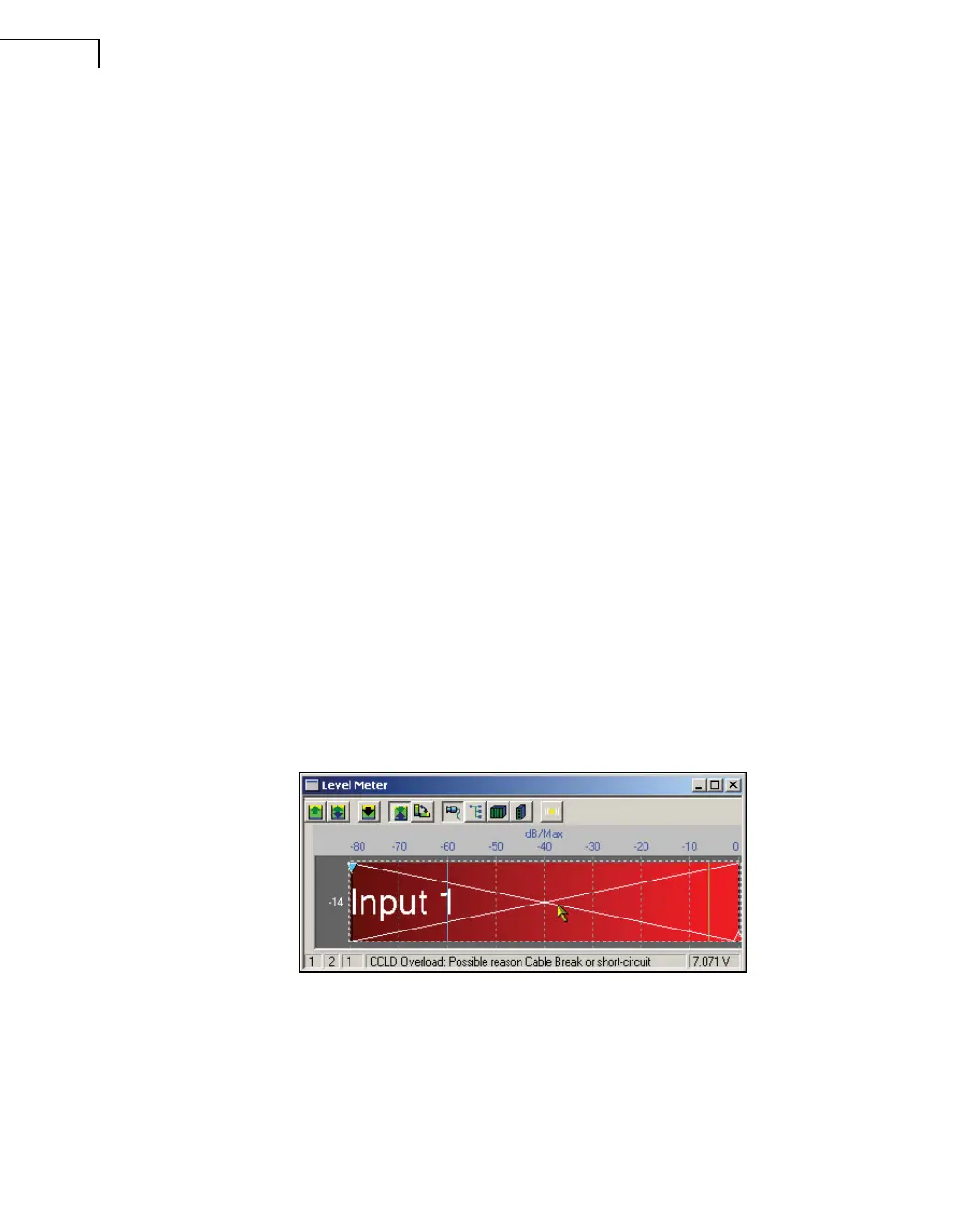
The status bar of the Level Meter in PULSE displays information about the possible causes
of an overload (see Fig.7.10).
Fig.7.10
The Level Meter’s status
bar shows possible
causes of overload
 Loading...