CHAPTER 6
Controller and Input/Output Modules
85
Inputs 2 to 4:
BNC connectors (see Fig.7.4 on page 89) for direct connection of a voltage signal
or for connection of CCLD transducers, for example, DeltaTron
®
accelerometers or microphone
preamplifiers, and 7-pin LEMO connectors (see Fig.7.6 on page 90) for use with Brüel & Kjær
microphones.
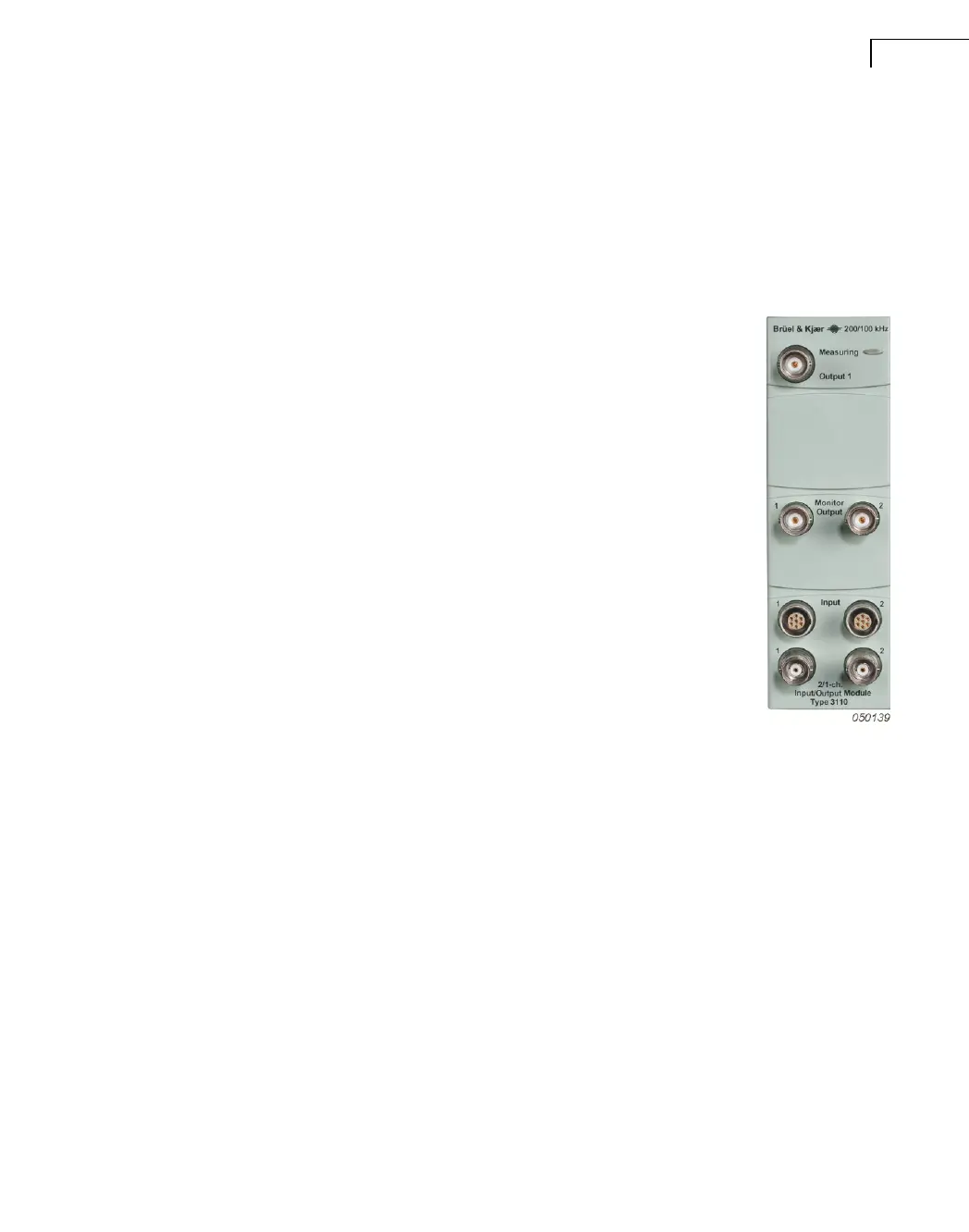
6.14 Generator, 2/1-ch. Input/Output Module Type 3110
Output
BNC connector (see Fig.7.5 on page 90) for output of a high-quality
generator signal over the frequency range to 102.4 kHz. The maximum
output voltage is 7 V
peak
delivered in one output range through a 24-
bit D/A converter. Output may be grounded or floating, controlled by
PULSE software.
Waveforms are determined by PULSE software and include:
• Sine – fixed or swept (burst or continuous)
• Dual sine – fixed, swept or combination
• Random (burst or continuous)
• Pseudo-random
• Periodic Random
• User-defined waveform (import from WAV file)
LEDs
Measuring: Indicates a measurement in progress or the downloading
of software to the module.
Input 1 and 2: For each channel, an LED indicates the status of the
channel (activated: green; overload: red). See section 7.8. The LEDs surround the connectors.
Monitor
Two BNC monitor outputs that are always active. These monitor signals taken from the last
amplifier before the anti-aliasing circuit, but after the high-pass filter. The output level is
2.236 V
peak
for full-scale input in any range. Output is buffered so that any connected circuit
does not influence the measurements.
Inputs 1 and 2
For input of signals in eight ranges from 7.071 mV to 22.36 V
peak
in 10 dB steps.
Note: The LEMO and BNT connectors of each input channel are independent. The BNT
connector is connected internally if voltage or CCLD input is selected in the PULSE soft-
ware, and the LEMO connector is connected if preamplifier input is selected. You can
therefore connect transducers to both inputs of one channel without affecting measurements.
 Loading...