PULSE Multi-analyzer System Type 3560-B/C/D/E – Installation and IDAe Hardware52
4.4 Grounding Considerations
Ground loops are a common problem in large vibration measurement installations. There are
different ways of avoiding this problem.
If an accelerometer is grounded to the test structure, the potential difference V
CM
between
the structure ground and the amplifier power supply ground (perhaps a few volts) may cause
a current to flow through the shield of the accelerometer cable and through the amplifier
circuits, introducing an error voltage which adds to the input signal.
To avoid this, the accelerometer can be isolated from the structure with an isolated stud and
a mica washer, when single-ended charge input is used. Most DeltaTron
®
accelerometers
have built-in insulators and thus are always isolated from the test structure and grounded
through the amplifier (see Fig.4.4).
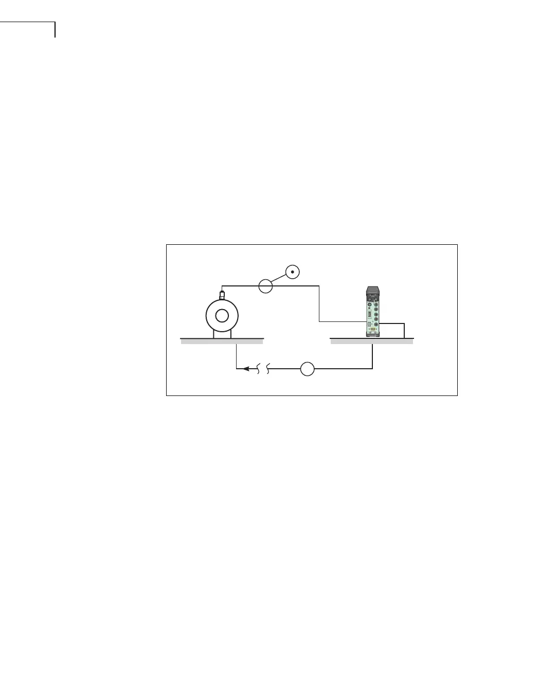
Fig.4.4
Avoiding ground loops
when using single-ended
(grounded) input
In other test situations, with charge transducers, this is not always a convenient solution. In
these cases, by selecting the floating input option you can separate the input and output
grounds and suppress ground loops. Because the ground potential difference (V
CM
) is
present in both the output signal from the input amplifier and the input ground, it is a
common mode signal for the differential amplifier which follows and does not appear at the
measuring amplifier’s output. The floating input mode will give typically 60 dB better
ground loop rejection (CMRR — Common-Mode Rejection Ratio) relative to single-ended
input mode.
Note: If you choose the latter solution (that is, select floating input), always ensure that the
test structure and input grounds are connected. Otherwise, single-ended input mode should
be selected (see Fig.4.5).
In multichannel applications ground loops will occur if more transducers (for example triaxial
accelerometers) have connection to the same ground structure. In such setups, magnetic
fields will induce current into the loop, causing noise signals. In such cases, the best solu-
tion is to select floating inputs, except for the most sensitive one which must be single-
ended, see Fig.4.6. As a result, the noise signals at all the floating inputs are suppressed
with the 60 dB CMRR and the single-ended input is not exposed to any V
CM
and subse-
quent noise signal. Ground loop problems can also occur with microphones, for example,
with a multichannel microphone array where the frame of the array is an electrical conductor
050301
Test Equipment
PULSE
Front-end
Accelerometer floating ⇒ Input type: Single-ended
V
CM
~
LAN
Tx
Rx
RS-232
Cable Lock
!
All Sockets
Aux. I/O
Input
5
2
1
Multi Frame Control
No
Yes
First or Last Frame
Output Tacho
Ext Power
Battery status
10 to 32v
Brüel & Kjær
On
/ O
f
f
B
attery status
Follow
Ex
t. Power
AUX
Power
Off On
 Loading...