CHAPTER 6
Controller and Input/Output Modules
69
RS–232
See section 7.2.
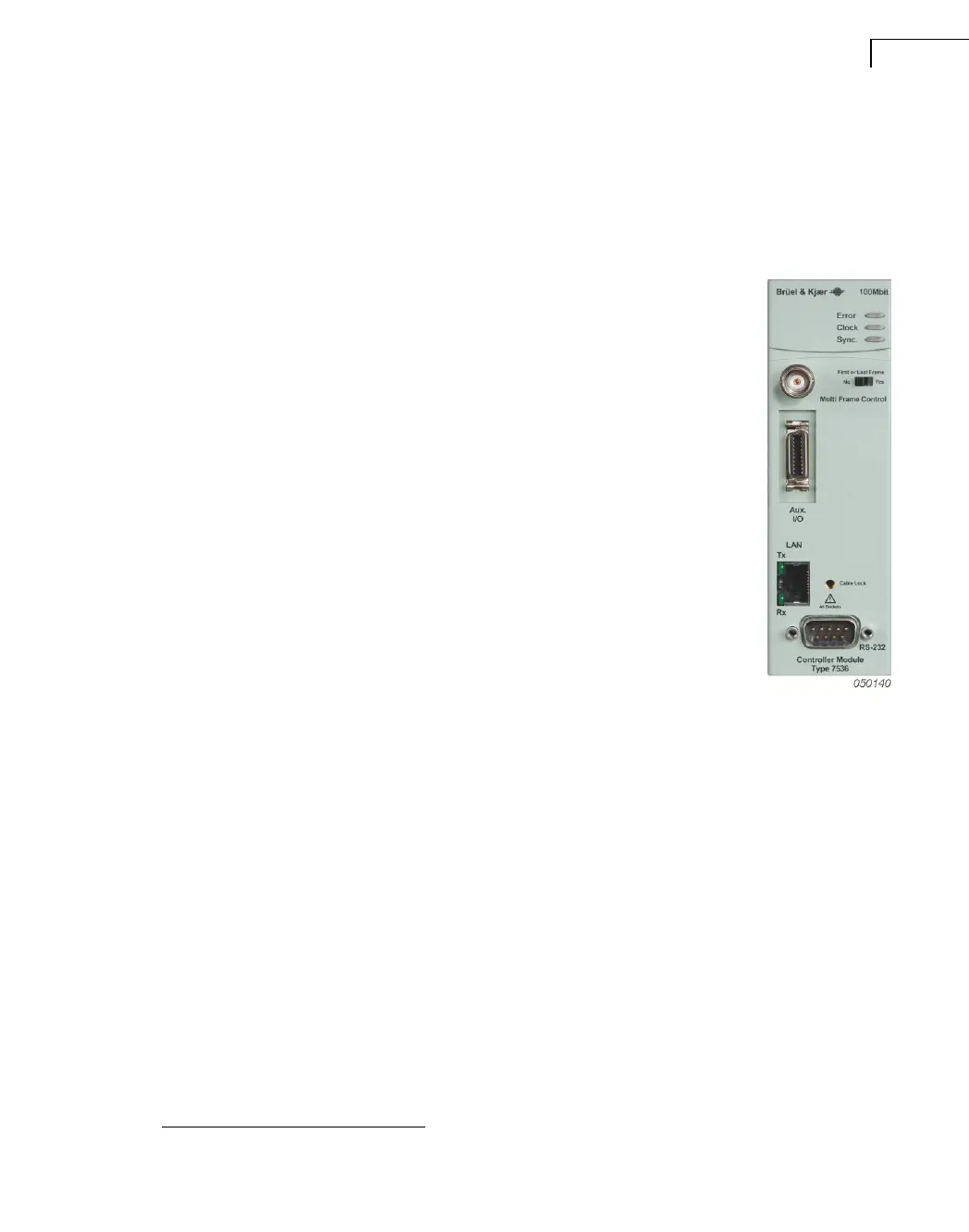
6.2 100 Mbit Controller Module Type 7536
LEDs
Error: Indicates if an error has occurred in the module.
Clock: Indicates the presence of a sampling clock and should always
be lit when PULSE software is running. If it is not lit, you cannot
make measurements.
Sync: Indicates the presence of synchronization signals.
Multi Frame Control and Synchronisation
This is used for switching the front-end on and off remotely so that
pressing any power button on any front-end will power up all front-
ends.
The connector is also used for multiframe control via AES/EBU. Con-
nect all the frames together with 50 Ω termination
a
at both ends using
standard 50 Ω cables of maximum length 100 m. The AES/EBU proto-
col contains both clock and sync. signals as well as power control. See
“AES/EBU and Types 7536, 7537, 7538, 7539 and 7540” on page 16.
Aux. I/O
See section 7.1.
LAN
The LAN RJ-45 connector is used to connect the front-end to LAN systems based on RJ-45
cables. The protocol complies with IEEE 802.3 10 base T.
RS–232
See section 7.2.
Cable Lock
Threaded hole for attaching LAN Cable Holder UA-1617.
a. A 50 Ω termination is built into these modules and is activated when First or Last Frame is set to Yes.
 Loading...