CHAPTER 6
Controller and Input/Output Modules
79
6.7.3 Type 3032-B
37-pin D-sub connector for inputs 1 to 6. See Fig.7.7 on page 91. Type 3032-B does not
support the use of microphones that require an external polarization voltage.
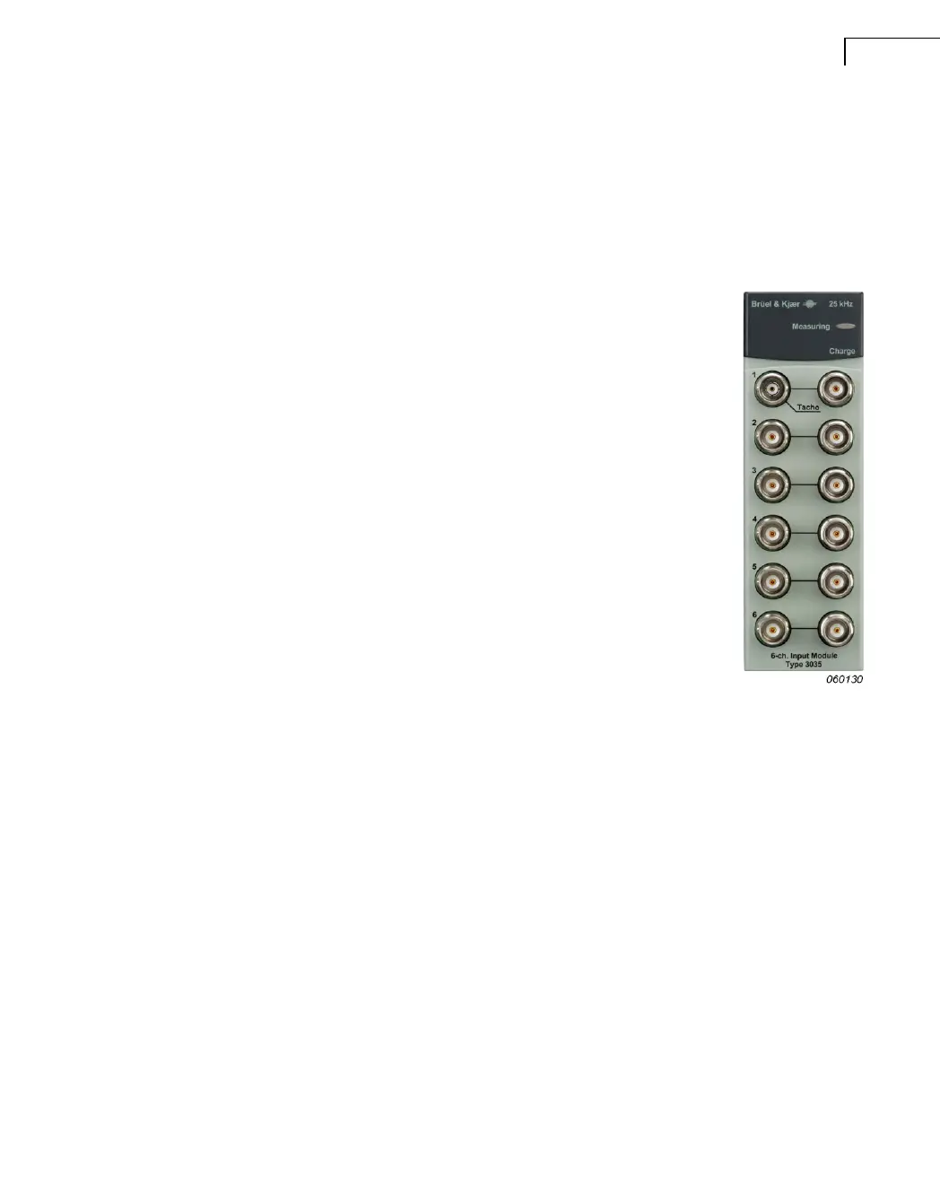
6.8 6-ch. Dyn-X Charge & CCLD Input Module Type 3035
6-channel Dyn-X Charge & CCLD Input Module Type 3035 is de-
signed specifically to allow the direct connection of charge transducers
to a PULSE system.
This module comes with BNT/BNC and TNC input connectors:
• BNT/BNC: For input of voltage/DeltaTron signals in one range to
10 V
peak
(dynamic range 160 dB) over the frequency range to
25.6 kHz
• TNC: For charge input in one of two input ranges: 1 nC
peak
or
10 nC
peak
The PULSE application you are running is used to determine whether
data is acquired from the applied BNC signal or the TNC signal. The
application also determines which of two working limits the charge
input is set to, 1 nC or 10 nC. The latter is useful for applications
where very high charge inputs can occur, such as gas turbine testing.
The module supports IEEE 1451.4 capable transducers with TEDS. In-
put may be grounded or floating, controlled by PULSE software.
LEDs
Measuring: Indicates a measurement in progress or the downloading of software to the
module.
Input 1 to 6: For each channel, an LED indicates the status of the channel (activated:
green; overload: red). See section 7.8. The LEDs surround the connectors.
Inputs
Input 1: BNT connector (see Fig.7.3 on page 89) for direct connection of a voltage signal
or for connection of CCLD transducers and TNC connector (see Fig.7.4 on page 89) for use
with charge transducers. The BNT connector also provides power for a tacho probe.
Inputs 2 to 6: BNC connectors for direct connection of a voltage signal or for connection
of a CCLD transducer, for example, DeltaTron
®
accelerometers or microphone preamplifiers,
and TNC connectors for use with charge transducers (see Fig.7.4 on page 89).
 Loading...