CHAPTER 5
Data Acquisition Units
65
5.5 Power Supply Module Type 2826
On/Off Button
This turns the system on or off. This function may also be controlled by
an external voltage supply (see “Follow Ext. Power Switch” below).
LEDs
Error: Red, indicating, for example, overheating. Switch off the equip-
ment and investigate the cause
On/Off: Red during power-up, green when all internal voltages are correct
Ext. Supply: Lit when an external power supply is connected
Follow Ext. Power Switch
The position of this switch determines the operation of the On/Off but-
ton. In the Follow Ext. Power position, the unit switches on when an
external power supply is connected and off when it is disconnected.
This makes it easy to turn the unit on and off when it is part of a mains
powered system.
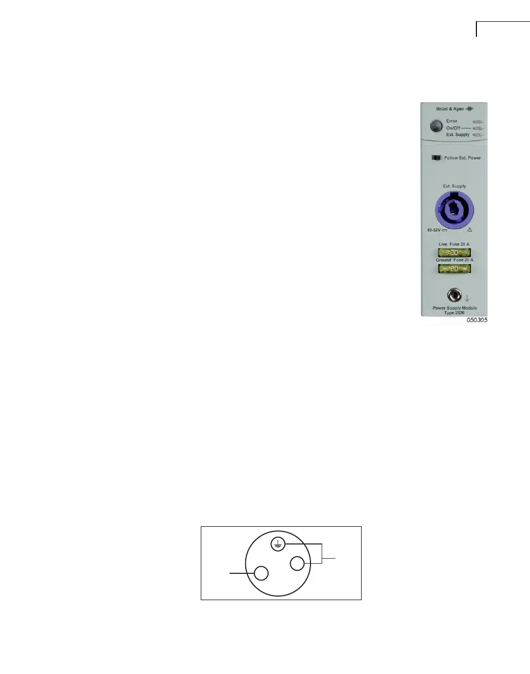
External Supply
A Neutrik
®
3-pole PowerCon connector allows the connection of a 10 – 32 V DC power
supply or a mains to DC converter. Mating connector: Neutrik
®
PowerCon NAC3FCA.
To disconnect the power cable, press the button on the connector, turn the connector to the
left and pull.
Power consumption is:
• 35 W nominal when supplying one input module
• 100 W nominal when supplying five input modules in a Type 3560-D
• 140 W nominal when supplying eight input modules in a Type 3560-E
Ensure that the cable can deliver at least 200 W.
Note: The total power consumption depends on the number of input/output modules and the
number of tacho probes in use. If all slots in the front-end are filled, a Type 3560-D can
power a maximum of four tacho probes, while a Type 3560-E can power two.
Fig.5.11
External supply connector
050310
Minus
N
L
Plus
 Loading...