8 (67) BRUKER BVT3000 Version 003
Description
0
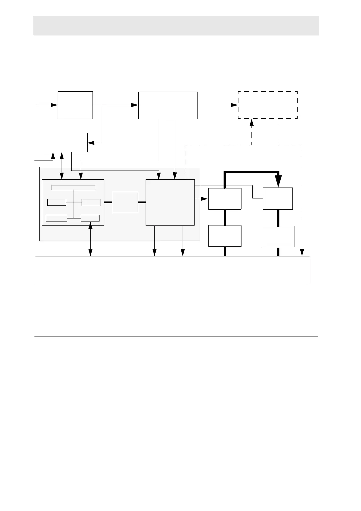
Figure 1.1. BVT3000 block diagram
BVT3000 main components 1.2
The interface board has a microcontroller for remote control of the BVT3000. Two
RS232 links are on this printed circuit. One link, on the front panel side, is for the
communication with host computer and the other for communication with the Eu-
rotherm 902 temperature controller.
A main toric transformer supplies the different groups. On the rear panel there is a
power supply plug. The thyristor bridge, for control of heater power, is also
housed in the rear panel. On the front panel a gas flow indicator (with a steel ball)
detects the gas flow. A device called valve block (a system of 4 valves) deter-
mines the gas flow and is under software control.
thermocouple
and Pt100
connector
RS232
Host computer
connector
probe heater
connector
BCU05
connector
Gas
inlet outlet
Gas
N2
option board for
LN2 evaporator
or exchanger
main
transformer
ac line
filter
Eurotherm
controller
microcontroller
POWER
CONTROL
& SECURITIES
OPTO-
COUPLERS
RAM
EPROM RS232
BUFF
VALVE
BLOCK
GAS FLOW
DETECTION
PRESSURE
REGULATOR
FLOW
INDICATOR