T104 Series Indicators EN-13
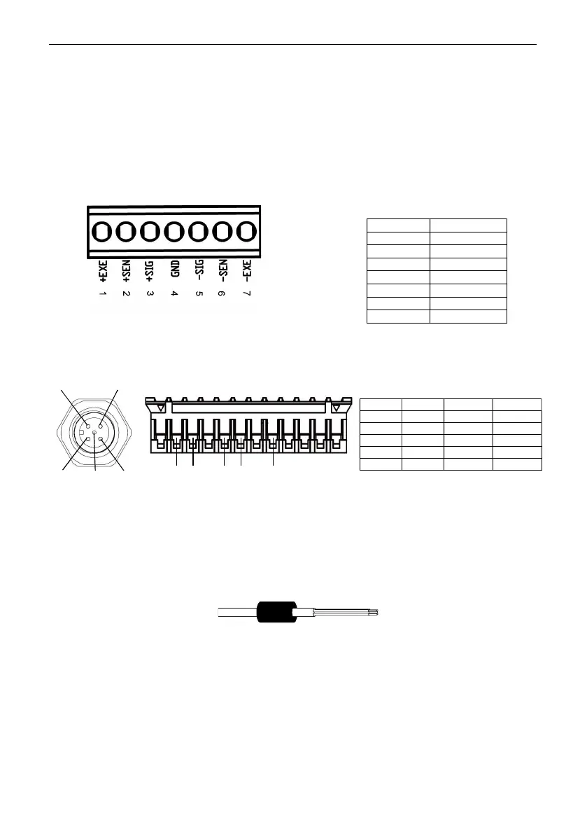
2.3.2.3 Load Cell Terminal Block Connection
Proceed with the previous section, to connect the load cell terminal block, first locate it on the mainboard
following the instruction in the previous two sections for the two models.
After finding the load cell terminal block, check Table 2-1 for the definition of each terminal screw connection
and make connections based on it. Please note that when using four-wire load cells, jumpers (the two short
wires supplied) must be placed between the +Excitation (+EXE) and +Sense (+SEN) terminals and between
the -Excitation (-EXE) and -Sense (-SEN) terminals.
The T104P and T104S indicators are designed to support both 2mV/V and 3mV/V load cells from the same
circuitry. A load cell output rating selection jumper is not required.
2.3.2.4 Load Cell Connection
After finding the load cell connector, check Table 2-2 for the definition of each pin.
11 10 8 7 5
Pin A Pin B
2.3.2.5 Installing the Ferrite Core
To meet certain electrical noise emission limits and to protect T104P and T104S from external influences, it is
necessary to install a ferrite core on the load cell cable connected to the indicator. The ferrite core is supplied.
To install it, simply route the cable through the center of the core. Either the complete cable or the individual
wires can be wrapped through it.
Figure 2-2 Ferrite Core
Number Connection
1 +EXE
2 +SEN
3 +SIG
4 GND
5 -SIG
6 -SEN
7 -EXE
Figure 2-1 load Cell Terminal Block
Table 2-1 Jumper Connections
1
2
3
4
5
Table 2-2 Jumper Connection
Pin A Pin B Signal Color
1 5 +EXE Red
3 7 +SIG Green
2 8 -SIG White
4 10 -EXE Black
5 11 SHIELD Pink
 Loading...