EN-4 T104 Series Indicators
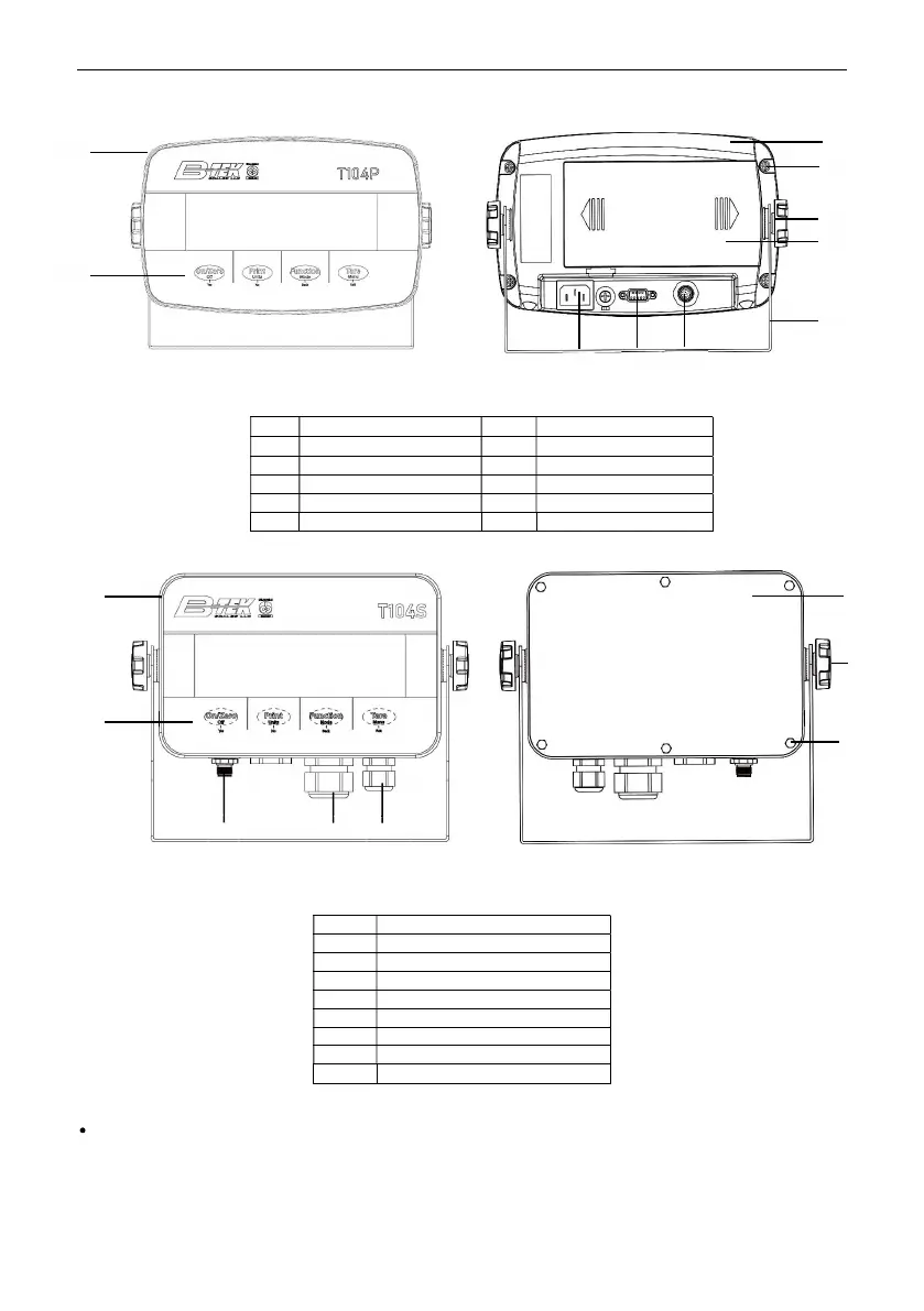
1.3. Overview of Parts and Controls
Figure 1-1 T104P Indicator
Figure 1-2 T104S Indicator
Item Description
1 Front Housing
2 Control Panel
3 Load Cell Connector
4 Strain Relief for Option
5 Strain Relief for Power Cord
6 Rear Housing
7 Adjusting Knobs (2)
8 Hex Head Bolts (6)
Note:
For some T104S models, the position of load cell connector, strain relief for option and power cord may
change. Please refer to the actual product.
Item Description Item Description
1
Front Housing 6 Battery Cover
2 Control Panel 7 Mounting Bracket
3 Rear Housing 8 Power Cord Connector
4 Screws (5) 9 RS232 Connector
5 Adjusting Knobs (2) 10 Load Cell Connector
1
2
1
2
8 9
10
4
5
7
6
3
3
4
5
6
8
7
 Loading...