Sensor Interface
SMART MATRIX MTC 1 - 4
Sensor Interface
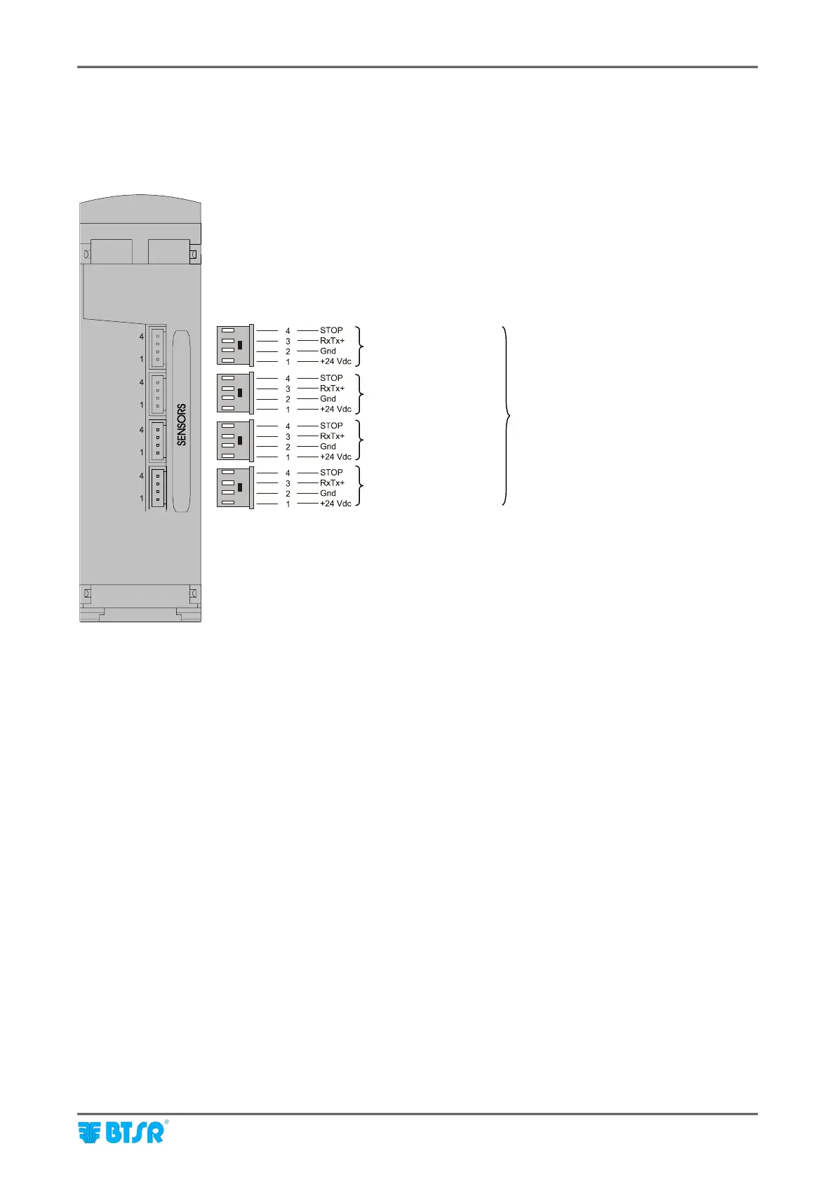
The following diagram shows the electrical interface (pin assignment) of SM-DIN to sensors connection.
As you may note, 4 identical connectors are available, allowing you to connect up to 4 IS3W/MTC.
The number of IS3W sensors actually connectable to the Board, depends on the capacity of power
supply system used.
Sensors
Sensors
Sensors
Sensors
Max 100 IS3W/MTC sensors
SM-DIN nn Module – (Identified by means of Edt function directly on the SM-DIN
module)