PC ↔ SMART MATRIX ↔ SM-DIN Connection
SMART MATRIX MTC 1 - 1
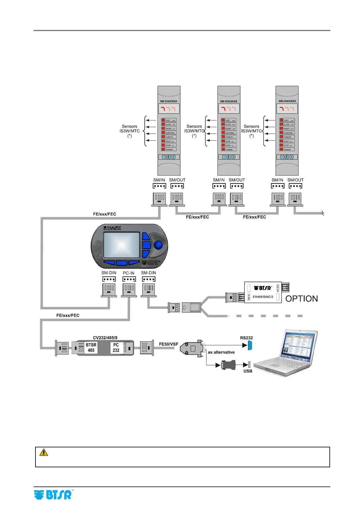
PC ↔ SMART MATRIX ↔ SM-DIN Connection
The following diagram shows the interconnections among: SMART MATRIX Terminal, SM-DIN Sensor
Interface Boards and PC.
The PC is mainly used for firmware update operations on SMART MATRIX Terminal.
(*) To connect the sensors, please refer to the following paragraphs:
SMART MATRIX
↔
SM-DIN
↔
IS3W/MTC Connection and Sensor Interface
Prior to operate the SMART MATRIX terminal, make sure you have programmed the communication
speed on all the SM-DIN/MTC Boards as well as on CV232/485/9 module.
For more details, please refer to paragraph SMART MATRIX
↔
SM-DIN/PC Interface on Section 1
and to paragraph ID and Transmission Speed Configuration on Each SM-DIN Board on Section 3.
On all electrical systems, you are kindly recommended to connect the ground cable (GND)
to the support on which the devices are installed.