SMART MATRIX ↔ SM-DIN/PC Interface
SMART MATRIX MTC 1 - 5
SMART MATRIX ↔ SM-DIN/PC Interface
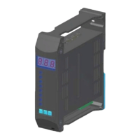
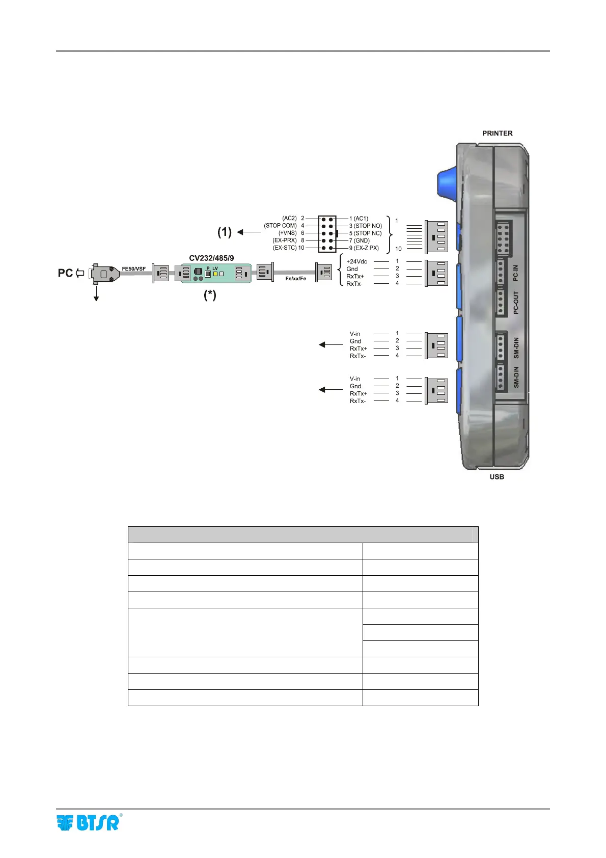
The following figure shows the electrical interface (pin assignment) of SMART MATRIX MTC terminal.
The “Printer” and “USB” connectors are not currently used for MTC application.
(*) Confirm that the LV green Led shows a double flashing (communication speed on
CV232/485/9 = 115 Kbps).
If necessary press the small P button.
SMART MATRIX Terminal Technical Characteristics
Power supply voltage 24 VDC ± 10%
Current absorption 100 mA Max
Protection fuse (SMART MATRIX) 1.5 A
Protection fuse (Sensor power supply) 1.5 A
0 – 24 VDC
VIL Max 1.2 VDC
Inputs
VIH Min 5 VDC
Operating temperature range +10° / +60° C
Storage temperature -25° / +85° C
Overall dimensions 140x80x31 mm
(1) As STOP output it is advisable to use the Relay contacts (STOP COM – STOP NO/STOP NC)
of this connnector, rather than the STOP signals provided by the SM-DIN MTC Boards.
.
SM-DIN/MTC
CV485/DAC/2
Port for software upgrade