Installation
3
RC35 programming unit - Technical specifications are subject to change without prior notice.
11
3.3 Installation and connection
The wall bracket can be attached directly to the wall or on a flush-mounting box.
When mounting on a flush-mounting box, note the following:
– Draughts from the flush-mounting box must not distort room temperature recording in
the programming unit (you may need to pack the flush-mounting box with insulation
material).
– Use the horizontal or vertical mounting holes (Fig. 3, 4).
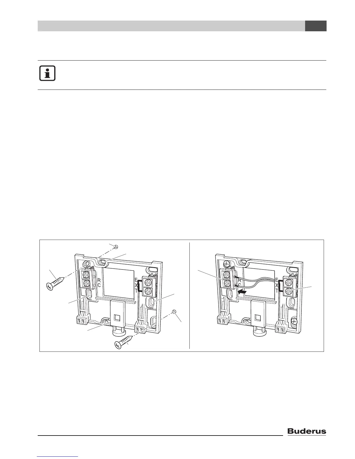
z Mount the wall bracket (Fig. 3, left).
z Connect the two-wire bus cable from the Energy Management System (EMS) to the
“RC” cable terminals (Fig. 3, 5).
– Cable type: 2 x 0.75 mm
2
(0.5 – 1.5 mm
2
), length max. 100 m
– The two wires are not polarity sensitive.
– Do not lay the cables next to power cables.
Fig. 3 Mounting the wall bracket (left) and connecting the wires (right)
1
Hole drilled in the wall
2
Screws (included with the unit) for surface-mounting on the wall
3
Vertical mounting holes for mounting on a flush-mounting box
4
Horizontal mounting holes for mounting on a flush-mounting box
5
“RC” terminals for EMS (boiler)
6
“EXT” terminals for external room temperature sensor or for jumper
Please use only the wall bracket with screw-type terminals.
z I
f there is a wall bracket without screw-type terminals already fitted, replace it.
1
2
3
4
3
4
1
2
5
6

 Loading...


