Troubleshooting
10
RC35 programming unit - Technical specifications are subject to change without prior notice.
45
10 Troubleshooting
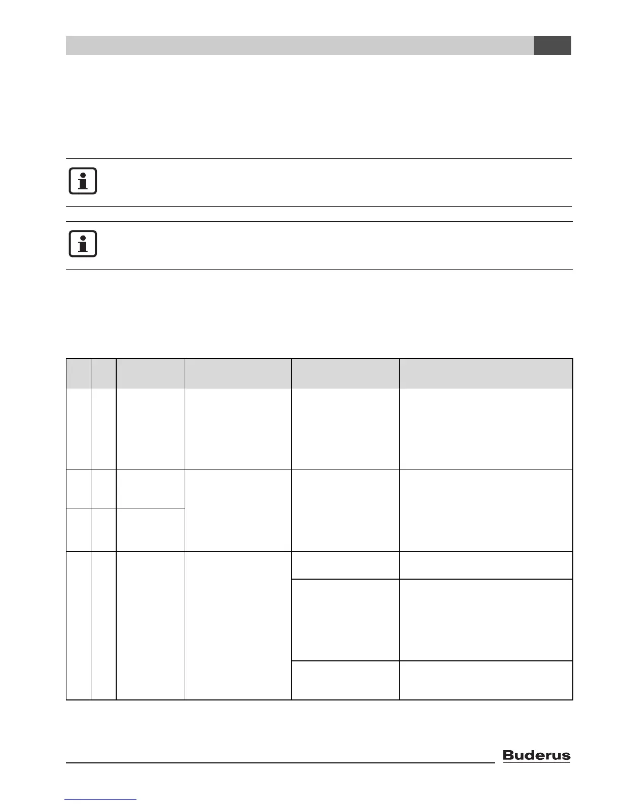
This fault table lists possible "plant errors", i.e. faults in EMS components. The heating
system keeps operating as much as possible in the event of a plant error; in other words,
heating of the home can continue.
Use only original Buderus parts. Losses caused by the use of parts not supplied
by Buderus are excluded from the Buderus warranty.
The faults displayed will vary depending on the specific type of boiler in use.
Abbreviations used:
SC =
Service code; x = heating circuit with the number x, e.g. A23 for heating circuit 3
FC = Fault code
HCx = Heating circuit with the number x
SC FC
Fault mes-
sage
Effect on control
characteristics
Possible cause Remedy
A01 800 Outside
sensor is
defect.
The minimum outside
temperature is used
instead of the actual
outside temperature.
Sensor incorrectly
connected or
installed.
Breakage or short cir-
cuit in the sensor lead.
Sensor is faulty.
z Check the sensor connection
and the sensor lead.
z Check that the sensor is cor-
rectly mounted.
z Compare resistance values with
the sensor characteristic curve.
A01 808 DHW sen-
sor 1 is
defect.
Heating of domestic
hot water is stopped.
Sensor incorrectly
connected or
installed.
Breakage or short cir-
cuit in the sensor lead.
Sensor is faulty.
z Check the sensor connection
and the sensor lead.
z Check that the sensor is cor-
rectly mounted.
z Compare resistance values with
the sensor characteristic curve.
A01 809 DHW sen-
sor 2 is
defect.
A01 810 DHW stays
cold.
The system continu-
ously attempts to heat
the DHW tank to the
set target tempera-
ture for DHW.
DHW priority is
switched off once this
fault message
appears.
Constant drawing or
system leak.
z Fix any leaks.
Sensor incorrectly
connected or
installed.
Breakage or short cir-
cuit in the sensor lead.
Sensor is faulty.
z Check the sensor connection
and the sensor lead.
z Check that the sensor is cor-
rectly mounted.
z Compare resistance values with
the sensor characteristic curve.
DHW pump incor-
rectly connected or
faulty.
z Check that the DHW pump is
working, e.g. by carrying out a
function test.
Table 19 Fault table

 Loading...


