Installation
3
RC35 programming unit - Technical specifications are subject to change without prior notice.
12
z If the RC35 is operated without an external room sensor, a jumper is required on the
“EXT”terminals (Fig. 3, 6) (the jumper is factory fitted).
z If the RC35 is operated with an external room sensor, the factory-fitted jumper on “EXT”
must be removed and the external room sensor must be connected there instead.
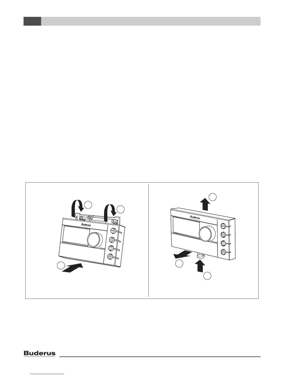
3.4 Attaching or removing the programming unit
Attaching the programming unit
z Hook the top of the programming unit onto the mounting plate in the direction shown
by the arrows (Fig. 4, A1).
z Push the bottom of the programming unit against the mounting plate in the direction
shown by the arrow until it clicks into place (Fig. 4, A2).
Removing the programming unit
z Press the button on the underside of the mounting plate in the direction shown by the
arrow (Fig. 4, B1) and pull the programming unit forward at the same time (Fig. 4, B2).
z Remove the programming unit by lifting upward (Fig. 4, B3).
Fig. 4 Attaching the programming unit (left) or removing it (right)
1
2
1
2
1
AB
3

 Loading...


