2007 Buell Firebolt: Chassis 2-73
HOME
INSTALLATION
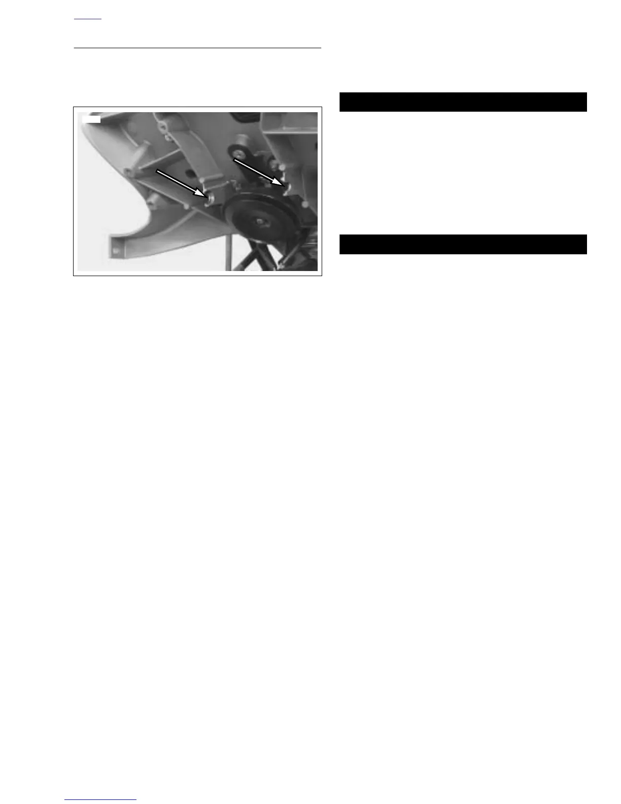
1. See Figure 2-104. Position headlight pivot fasteners into
groove of the headlight support bracket, flat side of nut
lined up with groove.
2. See Figure 2-103. Install headlight pivot fasteners (1) but
do not tighten.
3. Connect electronic control module. See 4.30 ELEC-
TRONIC CONTROL MODULE.
4. See Figure 2-102. Attach headlight connector to head-
light support bracket.
5. Connect headlight connections. See 7.12 HEADLIGHT.
6. See Figure 2-103. Rotate headlight support bracket up
(2) and tighten pivot fasteners (1) to 72-96 in-lbs (8-
11 Nm).
7. See Figure 2-101. Install electric control module.
a. Figure 2-103. Align electronic control module and
headlight support bracket with fairing support
bracket.
b. Tighten electronic control module fasteners (3) to
72-96 in-lbs (8-11 Nm).
8. See Figure 2-101. Connect flasher (1) and bank angle
sensor (2).
9. Install front fairing. See 2.37 FRONT FAIRING, WIND-
SHIELD, AND MIRRORS.
11WARNING1WARNING
Connect positive (+) battery cable first. If positive (+)
cable should contact ground with negative (-) cable con-
nected, the resulting sparks can cause a battery explo-
sion, which could result in death or serious injury.
(00068a)
10. Install battery by threading positive cable (red) into
threaded hole first tightening to 72-96 in-lbs (8-11 Nm).
See 1.5 BATTERY MAINTENANCE.
11WARNING1WARNING
After installing seat, pull upward on front of seat to be
sure it is in locked position. While riding, a loose seat can
shift causing loss of control, which could result in death
or serious injury. (00070a)
11. Install seat. See 2.38 SEAT.
Figure 2-104. Headlamp Pivot Groove
8460







 To Next Page