3-42 2007 Buell Firebolt: Engine
HOME
NOTE
Remove shop towel from entrance of throttle body to ensure
proper operation of induction module.
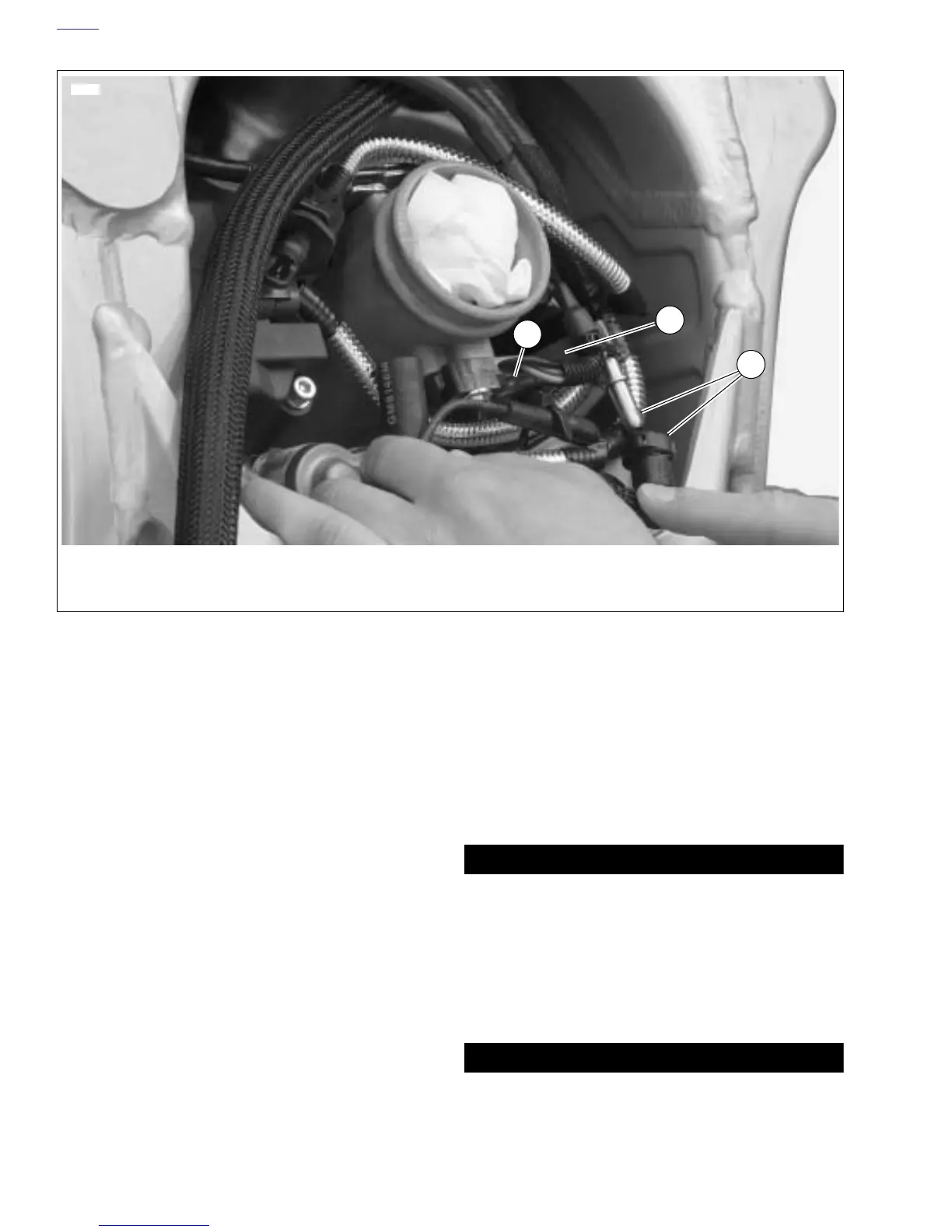
40. See Figure 3-55. Connect throttle position sensor [88]
(2).
41. Connect fuel injector leads [84 & 85] (3).
42. Connect fuel line (1).
43. Install throttle body velocity stack with retaining ring.
NOTES
● On XB models, velocity stack attaches to the throttlebody
with a wire spring clamp.
● On 1200 models, always check to ensure interactive
cable is adjusted and routed properly before installing air
box cover. See 1.17 INTERACTIVE EXHAUST CABLE.
44. Install air cleaner cover assembly. See 4.44 AIR
CLEANER ASSEMBLY.
45. Install intake cover assembly. Tighten fasteners to 12-36
in-lbs (1-4 Nm). See 2.34 INTAKE COVER ASSEMBLY.
46. Install oil filter and fill oil tank. See 1.6 ENGINE LUBRI-
CATION SYSTEM.
47. Connect fuel pump.
NOTE
The connection for fuel pump is just above the pump located
at the rear of the fuel tank on the left side of the vehicle.
48. Install rear belt and idler pulley. See 6.6 DRIVE BELT
SYSTEM.
49. Install left and right side rider footrests and support
plates. See 2.29 FOOTPEG, HEEL GUARD AND
MOUNT
50. Install sprocket cover. See 2.30 SPROCKET COVER.
51. Install chin fairing. See 2.33 CHIN FAIRING.
52. Install air scoops, right and left sides. See 2.35 AIR
SCOOPS.
11WARNING1WARNING
Connect positive (+) battery cable first. If positive (+)
cable should contact ground with negative (-) cable con-
nected, the resulting sparks can cause a battery explo-
sion, which could result in death or serious injury.
(00068a)
53. Connect negative ground cable to battery and install seat
(tighten).
11WARNING1WARNING
After installing seat, pull upward on front of seat to be
sure it is in locked position. While riding, a loose seat can
shift causing loss of control, which could result in death
or serious injury. (00070a)
54. Install seat. See 2.38 SEAT.
Figure 3-55. Fuel Line and DDFI Electrical Connections (Typical)
2
3
10646
1. Fuel line connection
2. Connection for throttle position sensor [88]
3. Connections for fuel injectors [84 & 85]
1