EN
72
5. Modes of operation
Hydraulic preconditions:
˳"ãò¯ĖÝÜÆ©òĐĐþ³òïòÆÜòĖïò³ööĂò³¨ãď³6 bar, a
pressure reducer (1) must be installed in the inlet.
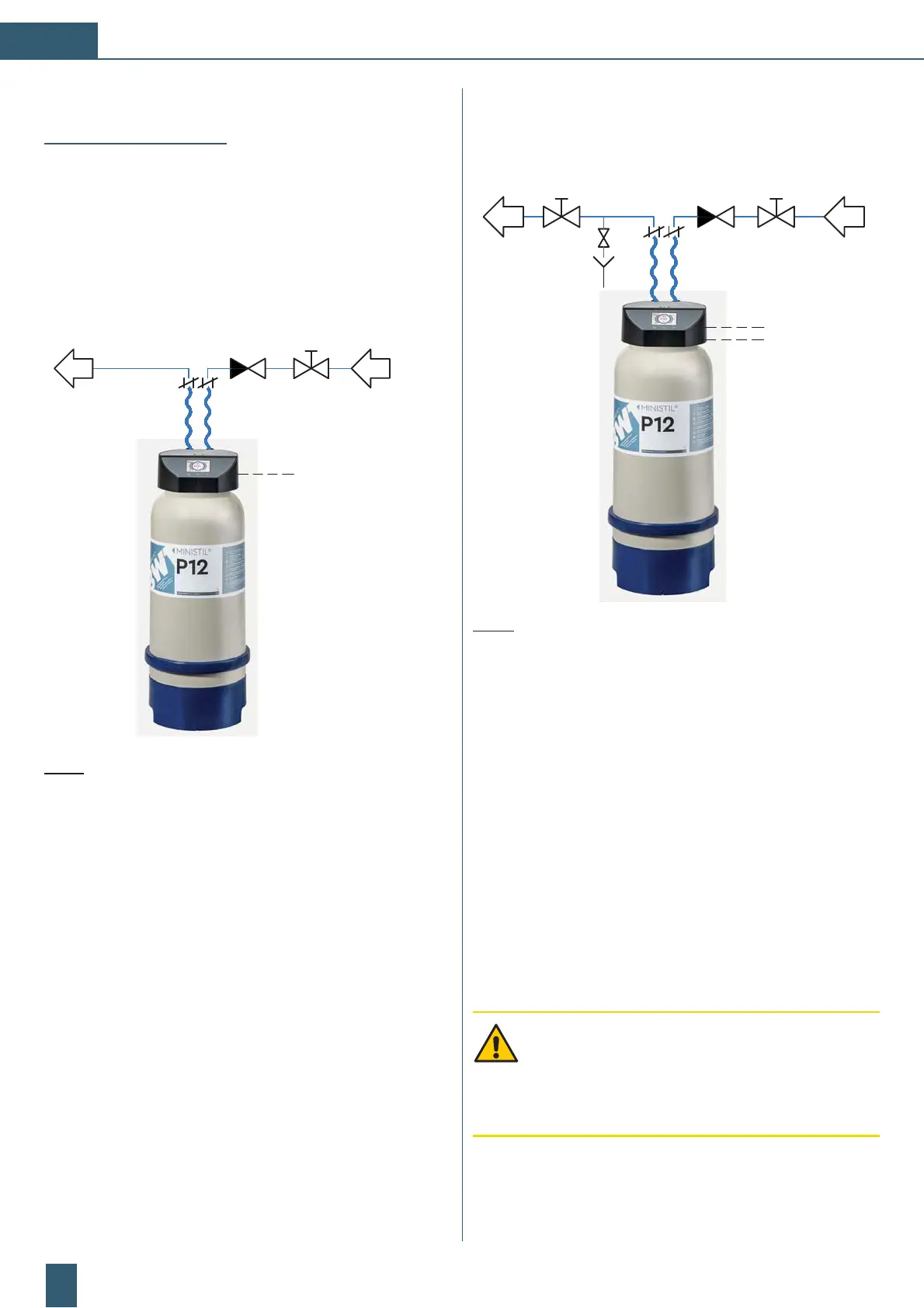
5.1 Operation without pressure
˳bó©òþòƯ¾³ã½þó@+A+Zb+:¯³ďÆ©³Ãö¨³³Ýď³Ýþ³¯
and is in the operating position, and the outlet is clear.
1
2
3
4
5
9-24V DC
6
Fig. 7: Operation position without pressure
(1) Manual shut-off valve
(2) Check valve
(3) Flexible fabric reinforced connection hose
(4)
Connection head
(5) Total deionisation cartridge
(6) Power adapter 9-24V DC
5.2 Operation with pressure
˳bó©òþòƯ¾³ã½þó@+A+Zb+:¯³ďÆ©³Ãö¨³³Ýď³Ýþ³¯˵Æö
in the operating position and is firmly connected.
1
2
3
4
5
6
7
9-24V DC
(Optional
alarm output
max. 24V/1A)
8
Fig. 8: Operation position with pressure
(1) Manual shut-off valve
(2) Check valve
(3) Flexible fabric reinforced connection hose
(4)
Vent valve
(5) Manual shut-off valve
(6) Connection head
(7) Total deionisation cartridge
(8) Power adapter 9-24V DC and
optional alarm output max. 24V / 1A
With this type of installation, the cartridge is always under
pressure. In the event of prolonged absences, the water
supply must be interrupted (weekends, holidays, etc.).
6. Hydraulic connection
CAUTION: The W3 guidelines for the creation of
water installations specified by the SVGW (Swiss
Water Industry Association) as well as the local
regulations apply to the installation.
Observe the safety instructions before installation.
 Loading...