EN
78
Remaining capacity
9. Operation and use
9.1 Basic design of the control unit
Color LCD display (digital):
The conductivity is measured at the cartridge outlet. The water flows through the conductance measuring probe
integrated in the control head or in the connection fitting. The digital electronics built into the control head or in the
conductance measuring device continuously monitor the conductivity.
When the set limiting value is reached, an alarm message is displayed.
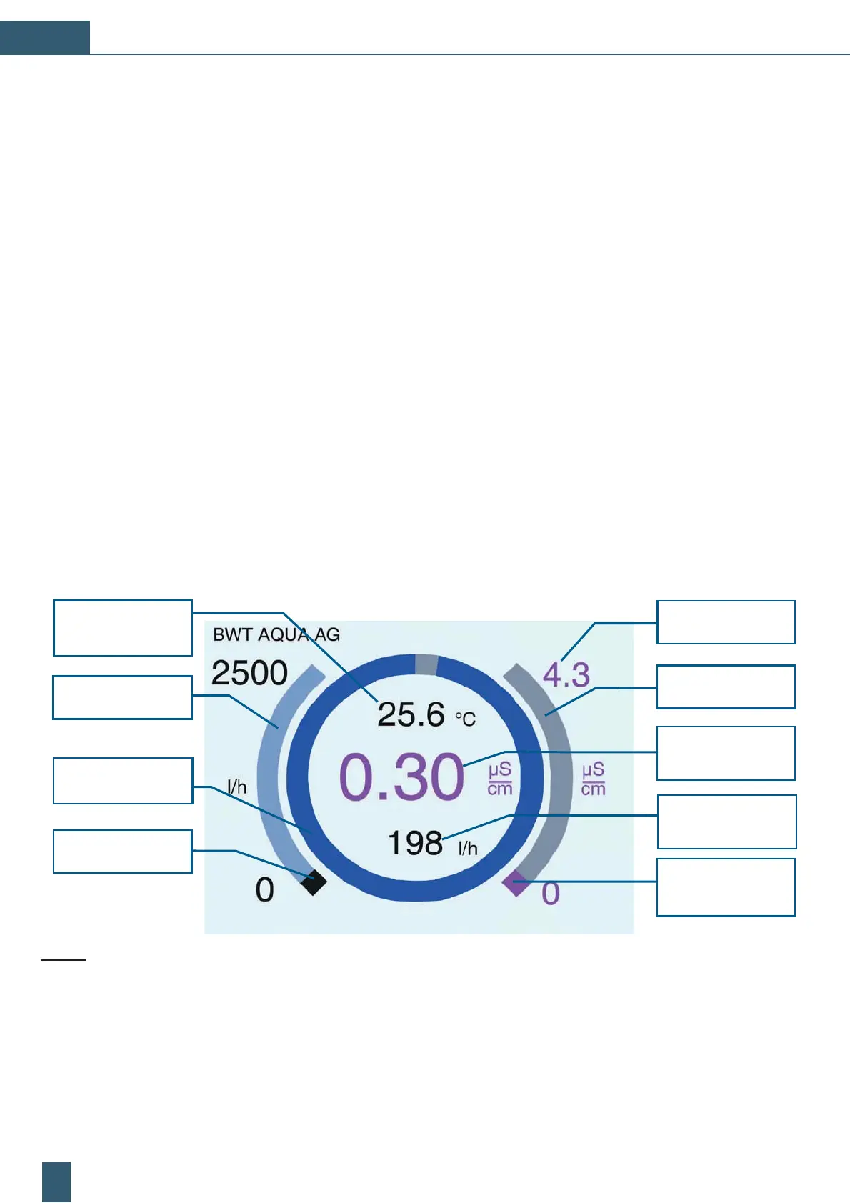
Functions of the digital display:
The digital display shows the value in S/cm.
˳ Ăòò³Ýþ©ãÝ¯Ă©þÆďÆþĖÆöÆݯƩþ³¯¨Ė©Æò©ĂÖò¨òãÝþóòƾÃþ
˳ Ăòò³Ýþ©ãÝ¯Ă©þÆďÆþĖÆööÃãĐÝöďÖĂ³ÆÝþó©³Ýþò³ã½þó¯ÆöïÖĖ
˳ Ăòò³ÝþňãĐÆöÆݯƩþ³¯¨Ė©Æò©ĂÖò¨òãÝþóֳ½þ
˳ Ăòò³Ýþþ³Üï³òþĂò³ÆööÃãĐÝöďÖĂ³¨ãď³þó©³Ýþò³ã½þó¯ÆöïÖĖ
For the no temperature measurement option, the value/display is omitted
˳ Ăòò³Ýþò³ÜÆÝÆݾ©ï©ÆþĖöã½þóþãþÖ©ï©ÆþĖÆööÃãĐݨĖɸɻɵ¯³¾ò³³¨ò
For the no flow measurement option, the bar still appears minus the « remaining capacity » label
˳ Ăòò³ÝþňãĐòþ³ÆÝÖÃ
For the no flow measurement option, the value/display is omitted
Standard display after start-up:
Temperature
real time
measurement value
Flow rate
measuring range
Capacity in real time
as benchmark
Flow rate real time
measurement value
Conductivity
limit-/alarm value
Conductivity
measuring range
Conductivity
real time
measurement value
Flow rate
real time
measurement value
Conductivity
real time
measurement value
The electronics are powered with 9V DC — the current consumption is less than 200 mA. The 9V DC inlet is protected
against polarity reversal. The maximum permitted voltage via this input is 24V DC. AC voltage is not permitted!
Fig. 22: Overview of the display functions



 To Next Page