EN
73
6.1 Installation place
NOTICE:
˳bóÆÝöþÖÖþÆãÝöÆþ³ÜĂöþ¨³½ò³³ã½½òãöþݯ
dry.
˳ãÝãþ³ĕ©³³¯þóܨƳÝþþ³Üï³òþĂò³˺
˳bóňããòöĂïïãòþöĂò½©³ÜĂöþ¨³ňþݯ
horizontal.
˳Sòãþ³©þþó¯³ďÆ©³½òãܩóÜÆ©Öö˵ïÆÝþ˵
solvents and fumes.
6.2 Hydraulic connection of head
types 1iD to 6iD
The following images show the connection options with
the various adapters and conductance measuring devices.
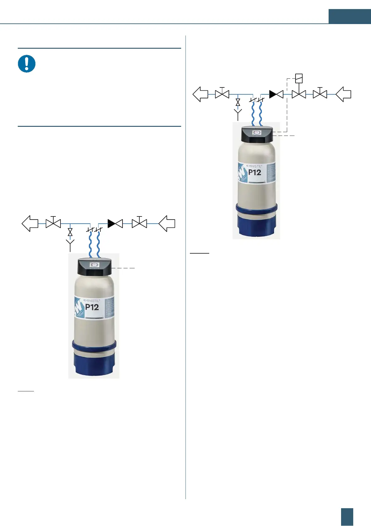
6.2.1 Hydraulic connection MINISTIL
connection head type 1iD
1
2
3
4
5
9V DC
via adapter
6
7
8
Fig. 9: Connection for MINISTIL connection head type 1iD
(1) Manual shut-off valve
(2) Check valve
(3) Flexible fabric reinforced connection hose
(4)
Vent valve
(5) Manual shut-off valve
(6) Connection head
(7) Total deionisation cartridge
(8) Electrical connection 9 V DC via mains adapter
6.2.2 Hydraulic connection MINISTIL
connection head type 2iD
1
23
4
5
24V DC
via adapter
6
7
8
Fig. 10: Connection for MINISTIL connection head type 2iD
(1) Manual shut-off valve
(2) Solenoid shut-off valve connected to the head
(3) Check valve
(4) Flexible fabric reinforced connection hose
(5)
Vent valve
(6) Connection head
(7) Manual shut-off valve
(8) Total deionisation cartridge
(9) Electrical connection 24 V DC via mains adapter
 Loading...