EasyManua.ls Logo

CAME 801QA-0050 User Manual

CAME 801QA-0050
40 pages
To Next Page IconTo Next Page
Page #1 background imageLoading...
Page #1 background image
ZLX24MA ZLX24MR
INSTALLATION MANUAL
FA0 1554-E N
EN English
Question and Answer IconNeed help?

Do you have a question about the CAME 801QA-0050 and is the answer not in the manual?

CAME 801QA-0050 Specifications

General IconGeneral
BrandCAME
Model801QA-0050
CategoryControl Panel
LanguageEnglish

Summary

General Precautions for Installers

Product Data and Information

Technical Data and Fuse Table

Specifications, operating parameters, and fuse ratings for ZLX24MA and ZLX24MR models.

Description of Parts

Installation Procedure

Preparing the Control Panel

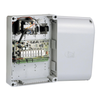
Steps for opening and preparing the control panel enclosure for installation.

Fastening the Control Panel

Electrical Connections

Preparing Electrical Cables

Guidance on connecting internal wires and properly using cable glands for external connections.

Power Supply Configuration

Mains Connection

Details on safely connecting the control panel to the 230V/120V AC mains power supply.

Gearmotor and Contact Capacity

Gearmotor Overview

Introduces different gearmotor types and their basic connection principles.

Gearmotor Wiring Diagrams (With Encoder)

Geamotors with Slowdown Switches

Geamotors Without Encoder

BUS CXN System Integration

BUS CXN System Overview

Explains the CXN CAME system, its two-wire bus, and connection methods.

Command and Control Devices

Safety Devices Installation

Advanced Safety Device Configuration

Programming Interface and Buttons

Programming Button Functions

Describes the function of the ESC, <>, and ENTER buttons for panel programming.

Leaf Speed, Slowdown, and Approach Points

Virtual Encoder and Function Menu

Virtual Encoder Operation

Manages gate travel using a virtual encoder for motors without physical encoders.

Input Configuration (CX and CY)

CX Input Function Assignment

Associates specific operational functions with the CX input terminal.

CY Input Function Assignment

Associates specific operational functions with the CY input terminal.

Function Settings (F5-F13)

Safety Devices Test

Verifies the correct operation of photocells after each opening and closing command.

Function Settings (F16-F21)

Function Settings (F23-F35)

Function Settings (F36-F44)

Partial Opening Adjustment

Determines the partial opening percentage for the M2 leaf relative to total travel.

Function Settings (F46-F63)

Wireless Safety Device Functions

RIO ED T1/T2 Functionality

Assigns specific functions to RIO ED T1 and T2 wireless safety devices.

RIO PH T1/T2 Functionality

Assigns specific functions to RIO PH T1 and T2 wireless safety devices.

Limit Switches and User Management

Limit Switch Type Configuration

Sets input operation for slowdown or end-of-travel limit switches.

Obstacle Removal Function

Manages obstacle detection and initiates leaf inversion to clear obstructions.

Transmitter and Motor Configuration

Radio Decoding Options

Chooses the type of radio coding for transmitters controlling the operator.

System Management and Security

BUS Inputs and Data Management

Error Messages and Final Operations

Error Message Reference

Lists potential error codes displayed by the control board and their corresponding meanings.

Related product manuals