28
48
9
1
6
10
9
3
4
5
7
8
2
11
(
(
(
Pag.
5 -
Manual code
:
119ES 87 ver.
2 01/2013
© CAME cancelli automatici s.p.a. -
The data and information reported in this installation manual are susceptible to change at any time and without obligation on CAME cancelli automatici s.p.a. to notify users.
ENGLISH
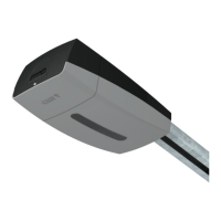
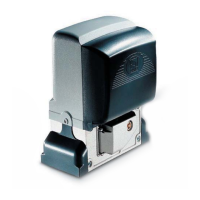
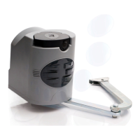
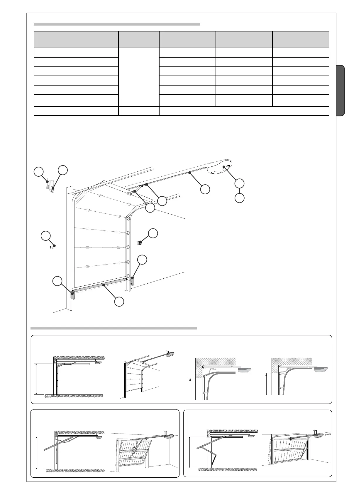
1 - Gearmotor unit
2 - Incorporated control panel with radio transmitter
3 - Transmission guide
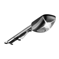
4 - Release device
5 - Standard transmission arm
6 - Key-switch selector
7 - Flashing light movement indicator
8 - Tuned antenna
9 - Safety photocells
10 - Indoor push button control
11 - Safety sensitive profi le
5.4 Applicative examples
* single sectional door * double sectional door
COUNTERWEIGHTED PARTIALLY RETRACTABLE SWING OUT
OVERHEAD DOOR
SPRING BALANCED FULLY RETRACTABLE SWING OUT OVERHEAD
DOOR
SECTIONAL DOOR
N.B.: if the cable length differs from that specified in the table, then you must determine the proper cable diameter in the basis of the actual
power draw by the connected devices and depending on the standards specified in CEI EN 60204-1.
For connections that require several, sequential loads, the sizes given on the table must be re-evaluated based on actual power draw and
distances.
When connecting products other than those mentioned in this manual please see the documents provided with the products themselves.
5.3 Cable list and minimum thickness
Connections Type of cable
Length of cable
1 < 10 m
Length of cable
10 < 20 m
Length of cable
20 < 30 m
230V power supply
FROR CEI 20-22
CEI EN
50267-2-1
3G x 1,5 mm
2
3G x 2,5 mm
2
3G x 4 mm
2
Flashing lamp 2 x 0,5 mm
2
2 x 1 mm
2
2 x 1,5 mm
2
Photocell transmitters 2 x 0,5 mm
2
2 x 0.5 mm
2
2 x 0,5 mm
2
Photocell receivers 4 x 0,5 mm
2
4 x 0,5 mm
2
4 x 0,5 mm
2
24V power supply to accessories 2 x 0,5 mm
2
2 x 0,5 mm
2
2 x 1 mm
2
Control and safety devices 2 x 0,5 mm
2
2 x 0,5 mm
2
2 x 0,5 mm
2
Antenna connection RG58 max. 10 m
 Loading...