4#!
3%.3
4#!
3%.3
!0#(
4#!
3%.3
&53-/4/2%!
&53
!##!
&53#%.42M!
#(
!02%
!0#(
!&
ON
OFF
/.
ON
OFF
4#!
3%.3
&53-/4/2%!
&53
!##!
&53#%.42M!
#(
!02%
!0#(
!&
Pag.
14 - Manual code:
119ES 87 ver.
2 01/2013 © CAME cancelli automatici s.p.a. - The data and information reported in this installation manual are susceptible to change at any time and without obligation on CAME cancelli automatici s.p.a. to notify users.
ENGLISH
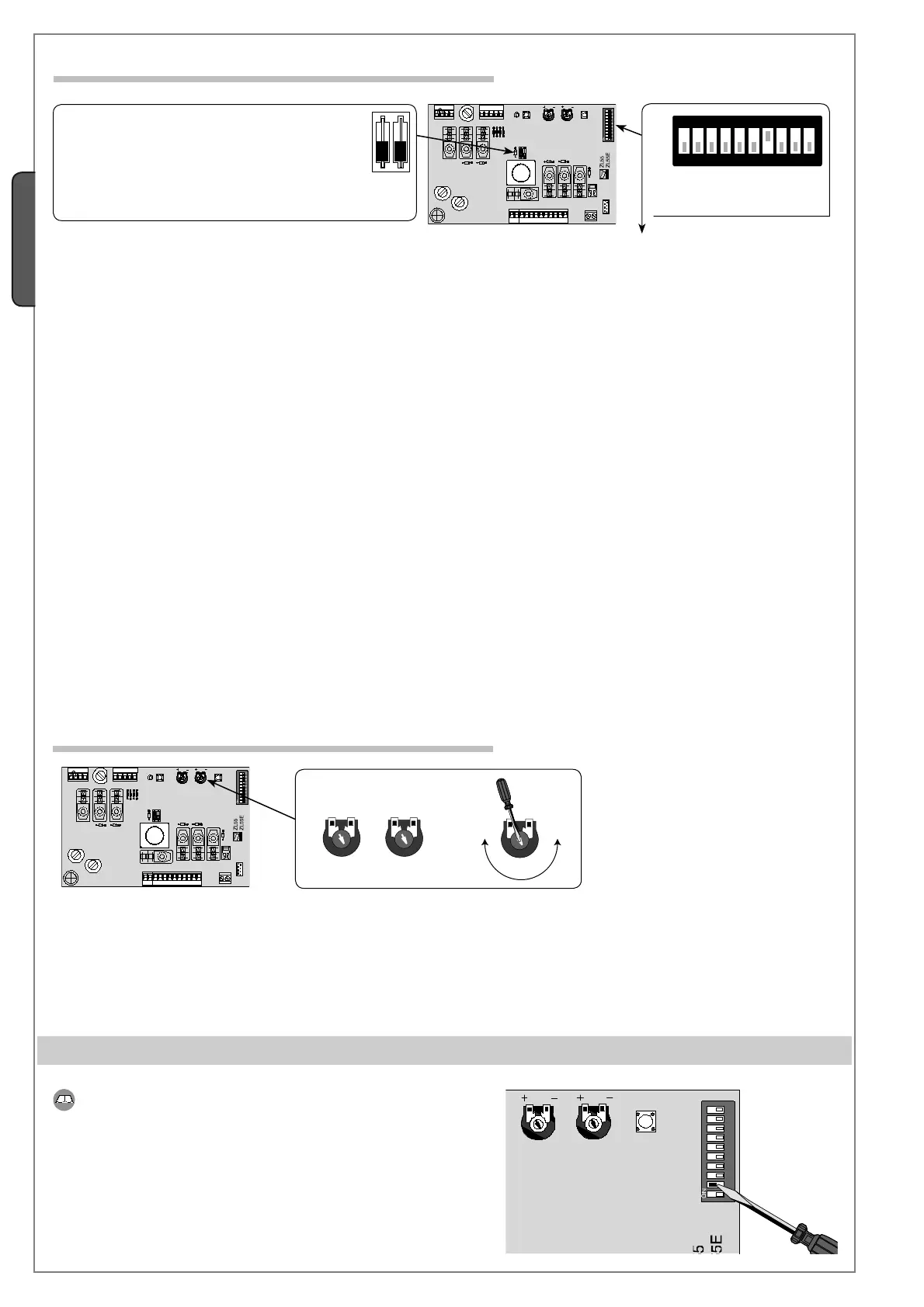
T.C.A. Trimmer = Adjusts the waiting time in the opening position. Once this time frame has lapsed, an automatic closing procedure is
performed. The waiting time may be adjusted to between 1 second and 120 seconds.
SENS Trimmer = Adjusts the amperometric sensitivity that controls the force of the engine developed during movement; if said force
becomes greater than the adjusted level, the system intervenes by inverting the direction of movement.
1 ON - Automatic closing - The timer for the automatic closing is activated when the door completes its opening cycle. The set time
is adjustable, and it is any how conditioned by the possible intervention of the safety devices and dies not activate after a total
safety ‘stop’ or during a power outage.
2 ON - “open-stop-close-stop” function with button (2-7) and radio transmitter (with radio frequency card inserted).
2 OFF - “open-close-inversion” function with button (2-7) and radio transmitter (with radio frequency card inserted).
3 ON - “open only” function with radio transmitter (with radio frequency card inserted).
4 ON - Pre-fl ashing upon opening and closing - Following an opening or closing command, the fl ashing light connected on 10-E,
fl ashes for 5 seconds before the cycle begins.
5 ON - Detection of obstacle - When motor is not running (gate closed, open or after a total stop command), prevents any movement
if the safety devices (e.g. the photocells) detect an obstacle.
6 ON - “Maintained action” the gate functions by keeping the buttons pressed (one button [2-3] for opening, and one button [2-7] for
closing).
7 OFF - Opening during closing cycle - if the photocells detect an obstacle during the gate’s closing cycle, the gate inverts its
direction until it is fully opened; connect the safety device to the terminals (2-C1), if unused, set DIP switch to ON.
8 - Disabled, keep the dip-switch in the ‘OFF’ position
9 - Disabled, keep the dip-switch in the ‘OFF’ position
10 ON - Enables the microswitch stop function when gate completely closes.
10 OFF - Enables the slowing-down function of the micro switch when gate is closing.
6.5 Adjustments
6.4 Function selection
7 Adjusting the run-limiters
For the closing cycle, either the stop or the slowing-down functions can
be selected.
Before starting any adjustment operations, position dipswitch 2 to ON
(this dipswitch has 10 positions) and make sure that the safety device is
connected to 2-C1. If there are no safety devices, then position dipswitch
7 to ON.
IMPORTANT: before performing any programming, read the
instructions carefully.
Dip-switch 10
1 OFF - Control unit designed to work with
V700 gearmotors
2 - Disabled, keep the dip-switch in the
‘OFF’ position
Dip-switch 2
 Loading...