6
6
4#!
3%.3
&53-/4/2%!
&53
!##!
&53#%.42M!
#(
!02%
!0#(
!&
+
-
23
1
2
3
4
5
6
7 8 9 10
11 12 13
14
15
16
17
18
19
20
21
53%/.,96&53%3
.
,
22
Pag.
11 -
Manual code
:
119ES 87 ver.
2 01/2013
© CAME cancelli automatici s.p.a. -
The data and information reported in this installation manual are susceptible to change at any time and without obligation on CAME cancelli automatici s.p.a. to notify users.
ENGLISH
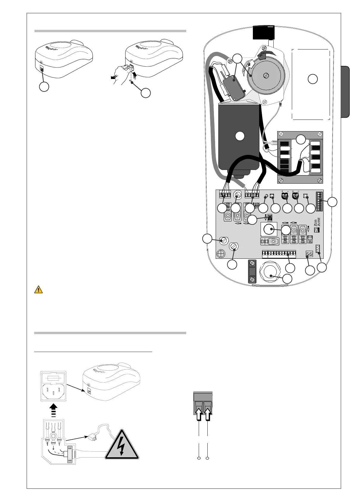
6.2 Main components
6.3 Electrical Connections
Power supply and accessories
Teminal board for accessories’ power supply:
- at 24V a.c. (alternate power) normally;
- at 24V d.c. (continuous power) when the emer-
gency batteries are in operation;
Maximum total power allowed: 40W.
1) 230V power socket
2) Line fuse 1.6A
3) Run-limiter unit
4) Emergency batteries’ slot
5) Gearmotor
6) Transformer
7) Morsettiera collegamento trasformatore
8) Fusibile motore 10A
9) Terminal to connect the gearmotor and run-limiter
10) Signal Led for radio-code
11) Radio-code save button
12) TCA Trimmer: adjustment of automatic closing cycle
13) SENS Trimmer: adjustment of amperometric sensitivity
14) Pulsante di comando per la regolazione dei finecorsa
15) Function selector (10 dip)
16) Function selector (2 dip)
17) Courtesy light
18) Accessories’ fuse 3,15A
19) Central control unit fuse 315mA
20) Accessories’ and control device connection terminal board
21) “AF” radiofrequency board socket
22) Electrical cable sockets
23) Radio antenna terminal board
Power supply
230V a.c. - 50/60 Hz
Warning! Before doing any work on the automation kit, cut off the pwer
supplì and disconnect the emergency batteries (if connected).
 Loading...