44
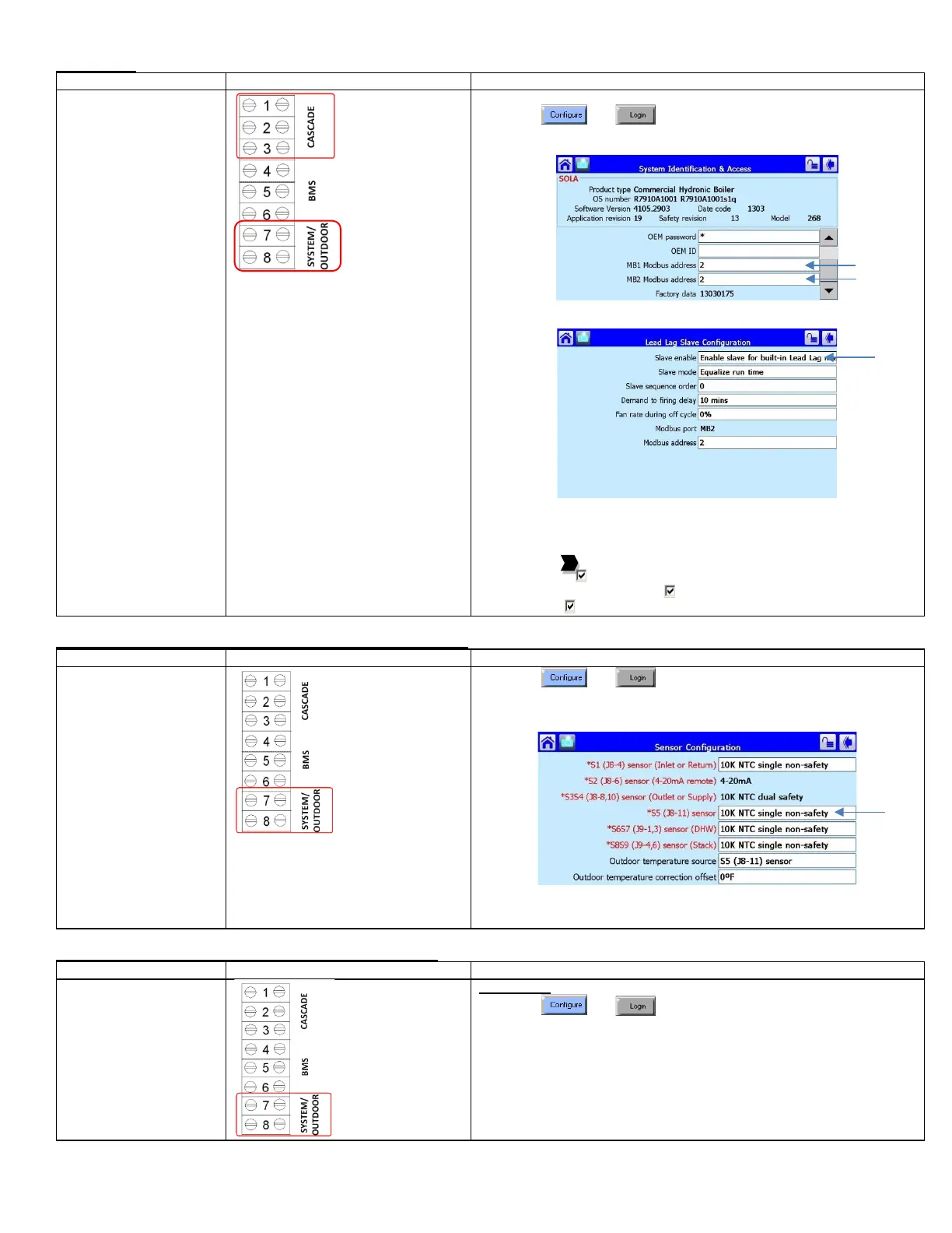
Slave Boiler
setup
• System temperature
sensor must be
connected to boiler #1.
• Outdoor temperature
sensor must be
connected to boiler #2.
1) Place toggle switch to LOCAL
2) Press and
3) Select System Identification & Access
4) Verify Modbus address. To be in sequential order
5) Select Lead Lag Slave Configuration
6) Select Slave Enabled = Enable slave for built-in Lead Lag master
The following steps are performed at the factory and verifying on site
will be sufficient:
7) Select Pump Configuration
8) Press [Advanced Options >>]
9) Press the to arrive at Central Heat Pump or DHW Pump
10) On Options: Local burner demand
11) On Options: Local Lead Lag Service Active
12) Force On: Outlet high limit
Master Boiler, System Sensor (Connected to Master Boiler #1)
sensor configuration
• System temperature
sensor must be
connected to boiler #1.
• Outdoor temperature
sensor must be
connected to boiler #2.
1) Press and
2) Press [Sensor Configuration]
3) Select S5 (J8-11) Sensor
4) Connector Type: 10K NTC Single Non-Safety
5) The control will proceed into a Lockout 2 condition
6) Press [Verify] > [Begin] > [Yes]
7) Press the reset button on the ignition control within the alotted time
Outdoor Sensor Connected to Slave Boiler 2 (ARH ONLY)
sensor configuration
• Outdoor temperature
sensor must be
connected to boiler #2.
• When done correctly,
the outdoor
temperature will be
shown on the Master
boiler
1) Press and
2) Press Sensor Configuration
3) Select S5 (J8-11) Sensor
4) Select Connector type = 10K single non-safety
 Loading...


