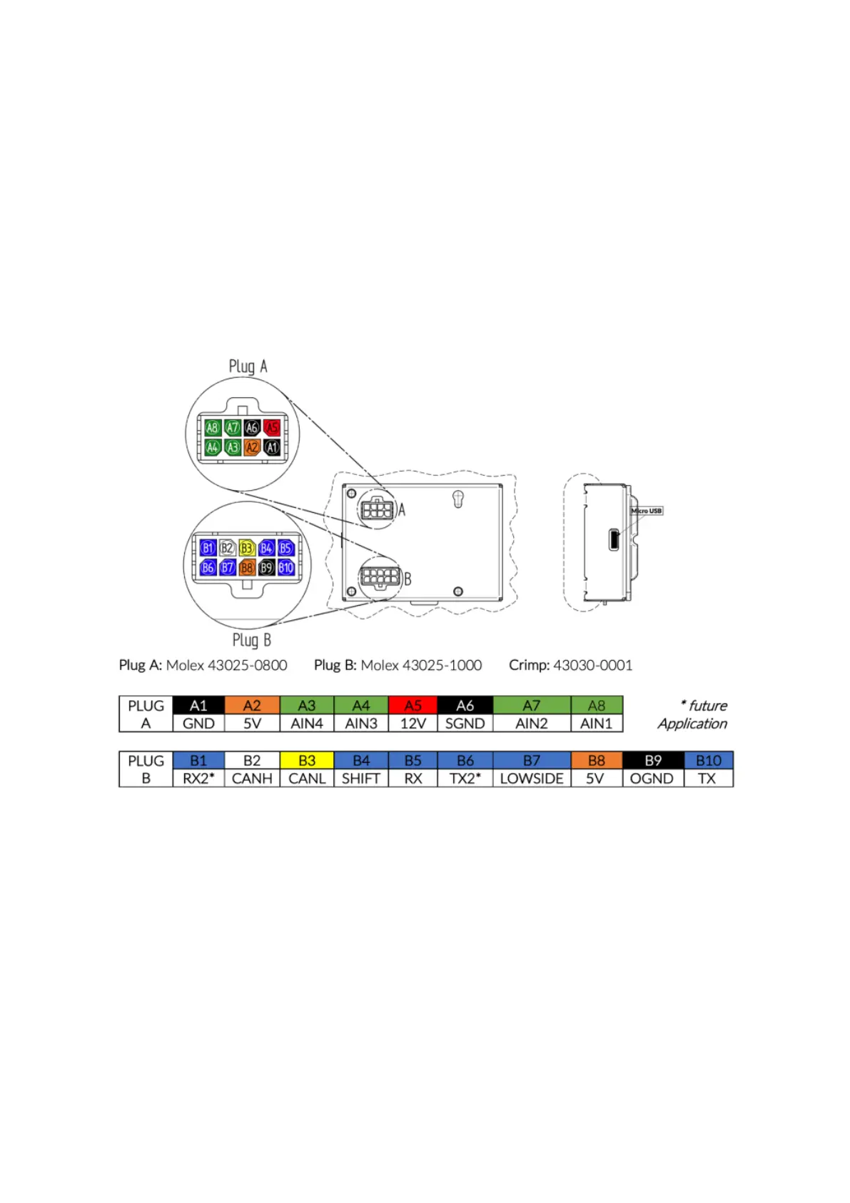
2 Connection of the plugs
To operate your MFD28/32 via the Can bus, only four wires are required:
• 12 volts on-board voltage, ideally ignition plus -> Pin A5
• Ground -> Pin A1
• Can High (CanH) -> Pin B2
• Can Low (CanL) -> Pin B3
Alternatively, you can replace 12 volts on-board voltage and ground with a USB power supply. For
operation in the vehicle, we expressly recommend a connection via 12-volt ignition plus and
ground. The wires of CanH and CanL are always designed as twisted pairs to minimize interference
signals.
Figure 1: MFD28/32 Pinout
Of course, CanH and CanL are not necessarily necessary for operation. Via the four analog inputs
(AINs – analog inputs) you can also feed the 0-5 volt voltages of analog sensors into the display and
have them converted by the display and displayed on it.
By default, our AINs are preconfigured for different sensors:
• AIN1: Oil Temperature (OilT) -> Pin A8
• AIN2: Abgastemperatur (EGT) -> Pin A7
• AIN3: Oil pressure (OilP) -> Pin A4
• AIN4: Ladedruck (MAP) -> Pin A3
The power supply for operating the analog sensors can also be realized directly via the display. Pin A2
and pin B8 are 5V during operation, and the sensor ground can be obtained from SensorGround A6.
The maximum current of 0.5 amperes should not be exceeded.