Chapter 3
3-12
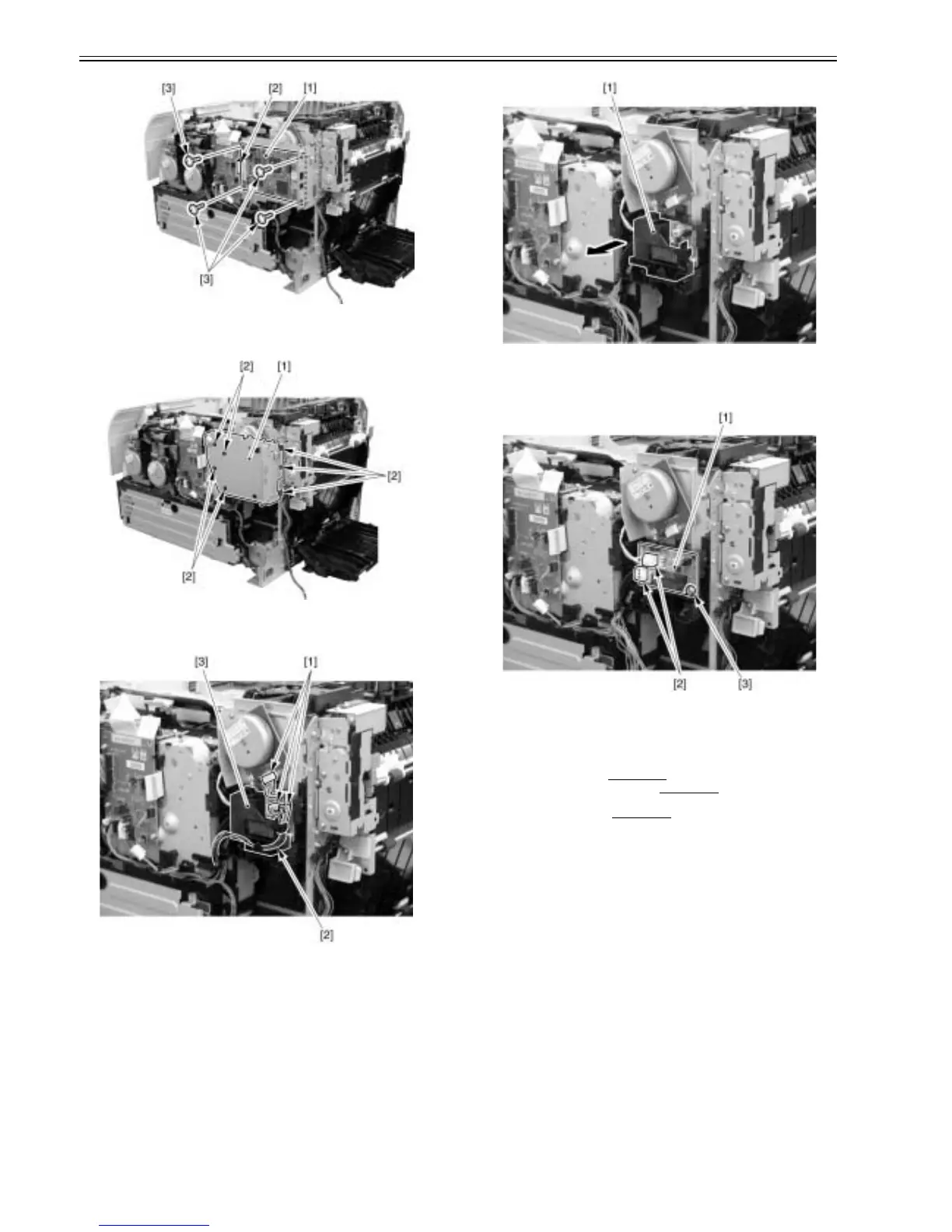
F-3-48
2) Remove the sheet metal [1] of the main controller PCB.
- 7 screws [2]
F-3-49
3) Remove 3 connectors [1], and remove the cable [2] from the cable guide
[3].
F-3-50
4) Remove the cable guide [1].
F-3-51
5) Remove the sub power supply PCB [1].
- 2 connectors [2]
- 1 screw [3]
F-3-52
3.1.13 Driver PCB
3.1.13.1 Pre-procedure for removing driver PCB
0021-3967
1) Remove the right cover.(page 3-3)Reference[Removing right cover]
2) Remove the upper rear cover (left).(page 3-1)
Reference[Removing up-
per rear cover (left)]
3) Remove the upper cover.(page 3-5)
Reference[Removing upper cover]
3.1.13.2 Removing driver PCB
0021-3968
1) Remove the driver PCB [1].
- 1 flat cable [2]
- All connectors on PCB (11 connectors)
- 3 screws [3]



 To Next Page