9
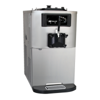
Models C708/C709/C716/C717
Introduction
050920
Pump Motor Rotation
1. Remove the air/mix pump assembly.
2. Connect power to the freezer and place the
power switch in the ON position.
3. Press the PUMP symbol on the control panel.
This will activate the pump motor only.
4. Observe the pump ball crank. It should be
rotating counterclockwise.
If rotation is not correct, refer to the wiring diagram
on the pump motor and re-wire accordingly.
Note: Repeat these steps for the other side on the
model C716 & C717.
REMEMBER TO DISCONNECT ALL
POWER TO THE FREEZER! Failure to follow this
instruction may result in electrocution or severe
personal injury from hazardous moving parts.
Electrical Connections
Each freezer requires one power supply. Check the
data label on the freezer for fuse, circuit ampacity
and electrical specifications. Refer to the wiring
diagram provided inside the control box for proper
power connections.
In the United States, this equipment is intended to
be installed in accordance with the National
Electrical Code (NEC), ANSI/NFPA 70-1987. The
purpose of the NEC code is the practical
safeguarding of persons and property from hazards
arising from the use of electricity. This code contains
provisions considered necessary for safety.
Compliance therewith and proper maintenance will
result in an installation essentially free from hazard!
In all other areas of the world, equipment should be
installed in accordance with the existing local codes.
Please contact your local authorities.
Stationary appliances which are not equipped with a
power cord and a plug or other device to disconnect
the appliance from the power source must have an
all-pole disconnecting device with a contact gap of at
least 3 mm installed in the external installation.
Installation of Optional Syrup Rail
X48015-27 (C708 & C709 Only)
The syrup rail can mount to only the left side of the
C708 or C709 if the top air discharge chute is not
used.
The syrup rail can be mounted to either the left or
right side of the C708 or C709 units if a top air
discharge chute is used.
Perform the following steps to mount the syrup
rail on the side of a unit where a top air
discharge chute is not installed:
1. Remove the (4) panel screws as shown in
Figure 5.
Figure 5
2. Install the Mounting Assembly – Syrup Rail
(X57317) using the (4) Spacers (053600) and
the (4) Screws-1/4-20X3 HEX CAP (025984)
with (4) Washers (000655).
3. Install the (4) Plugs – Square Tubing (057381)
in the ends of the Mounting Assembly – Syrup
Rail (X57317).
4. Install the (3) Holding Collars (046551) using
the (3) Screws-10-32X3/4 OVAL HD-SS.
5. Hang the Syrup Rail Assembly (048015-27) on
the holding collars.